1.1.2 Input stage
The L1 input stage is equipped with both balanced and single-ended types of connections, 4x XLR, 2x RCA and 2x BNC. A high
bandwidth, high performances discrete amplifier buffers the signal prior to applying the volume. A DC blocking capacitor can be
engaged to remove unwanted DC offset coming from sources connected to the L1's inputs. For more information about this
feature, please refer to section 1.2 Advanced DC offset cancellation.
1.1.3 Volume control
The L1 volume control is based on a discrete 20 bits R-2R resistor network circuit topology, providing a range of 118dB in 0.5
steps. The volume set by the user from the front panel rotary knob or from the remote control is translated by the main controller
into commands that open or close analog switches, creating a different combination of resistors for each of the volume steps,
therefore applying the required attenuation. A gain of up to 18dBs is available for sources providing low output levels. A Mute
function is also available.
1.1.4 Output stage
The L1 output stage is equipped with both balanced and single-ended types of connections, 2x XLR, 1x RCA and 1x BNC. A
powerful, high bandwidth, high performances discrete amplifier provides with ample current to drive one or more outputs
simultaneously.
1.2 Advanced DC offset cancellation
DC (continuous) voltage in an R-2R resistor network circuit topology translates into audible clicks in the audio signal when a
volume change is applied. In order to remove the clicks, DC offsets must be canceled. The L1 features an advanced DC offset
cancellation system allowing to reduce the DC voltages to insignificant levels, preventing audible clicks from happening. The DC
offset cancellation system works in parallel with the audio path. It acts on the DC component of the audio signal only, leaving the
audio content unaltered, but DC free. Eight pick up points are measured and corrected in real time throughout the signal path,
ensuring all stages including the L1 outputs are DC free.
DC offset wise, if there is one thing the L1 cannot control, it is the DC inherited from the pieces of equipment connected to its
inputs. Although care has been taken to try and counteract a fair amount of DC offset from upstream pieces of equipment
connected the its inputs, if these pieces of equipment exhibit high levels of DC at their outputs, the L1 will reach a state where it
can't counteract the inherited DC any more. If this condition happens, clicks might start to become audible when a volume change
is applied. The only way to remove the excessive DC offset is to add a capacitor in series with the signal path. The L1 front panel
display indicates that it cannot counteract DC any further and recommends to engage the DC blocking capacitor. By default, there is
no capacitor in series inside the signal chain, however the large value high-grade polypropylene capacitor can be engaged when
excessive DC coming from the upstream piece of equipment has been detected at the input. Please note that engaging the
capacitor is a recommendation only, it is up to the user to engage the capacitor or not. It is done from the unit's menu, but in no
circumstances will the unit engage the DC blocking capacitor automatically. The DC blocking capacitor is engaged on a single input
basis, it is not a global setting for all the inputs.
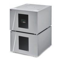
1.3 Careful Metal Work Construction
The L1 preamplifier chassis is made of high grade aluminum alloy with no visible screws on the front, top and side panels. First
class mechanical and chemical surface treatments provide the luxury finish of the L1. Pin assembly of all chassis elements enables
10 L1 User Manual Rev 1.0