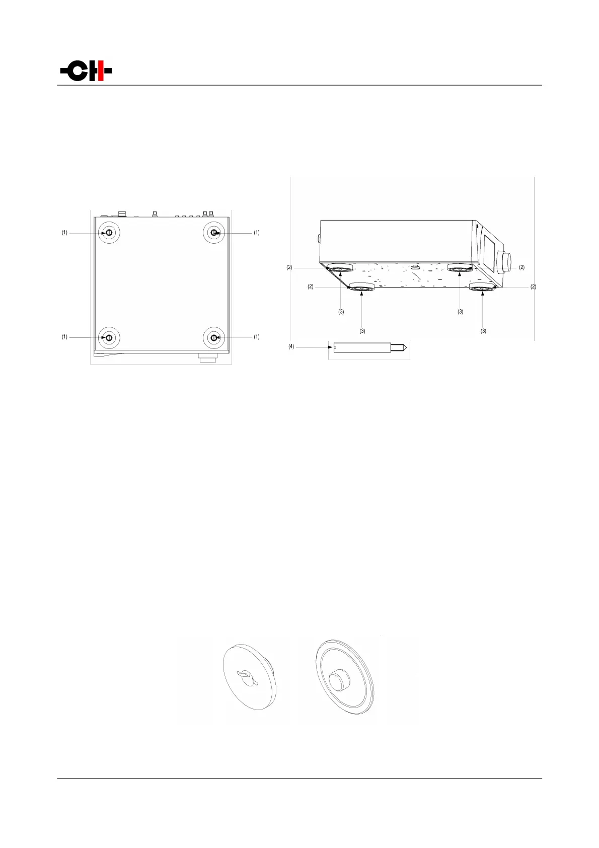
adjustment spikes are located in the accessory box and the L1 sits on elastomer rings to protect the base.
Insert the adjustment spikes into each foot. Please use the provided screwdriver to screw the spikes into the feet and make the
level adjustments. Optional CH support discs have been designed to optimally couple the spikes with the rack on which the L1 sits,
simultaneously ensuring vibration channeling outside the system and decoupling from external vibration sources.
Adjustment shafts, feet and spikes
(1) Adjustment shafts. Insert the adjustment spikes and use the provided screwdriver to secure and adjust individual spikes
(2) Feet
(3) Adjustment spike heads (when inserted into the adjustment shafts)
(4) Adjustment spike
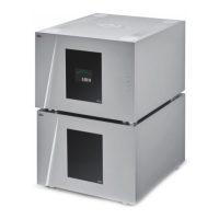
3.2.2 Shaft covers
There are two types of shaft covers delivered with your L1 unit. One type of shaft covers (stacking covers, made of steel) is used
when multiple CH units are stacked. This type of cover includes a receptacle to receive the corresponding spike of the unit placed
just above it. By doing so, mechanical vibrations are optimally transmitted to ground and minimized inside the units. The second
type of shaft cover (top cover, made of aluminum) can be used when units are not stacked or for the top unit when stacked. It
covers the shaft and provides a smooth finish to the top unit. Shaft covers are located in the accessory box delivered with your L1
unit.
Never stack any component other than CH's on your L1. Never use the aluminum shaft covers (top covers) when another CH
component is to be stacked on top of your L1.
Shaft covers (left: stacking cover, right: top cover)
16 L1 User Manual Rev 1.0