Install the Protector System
®
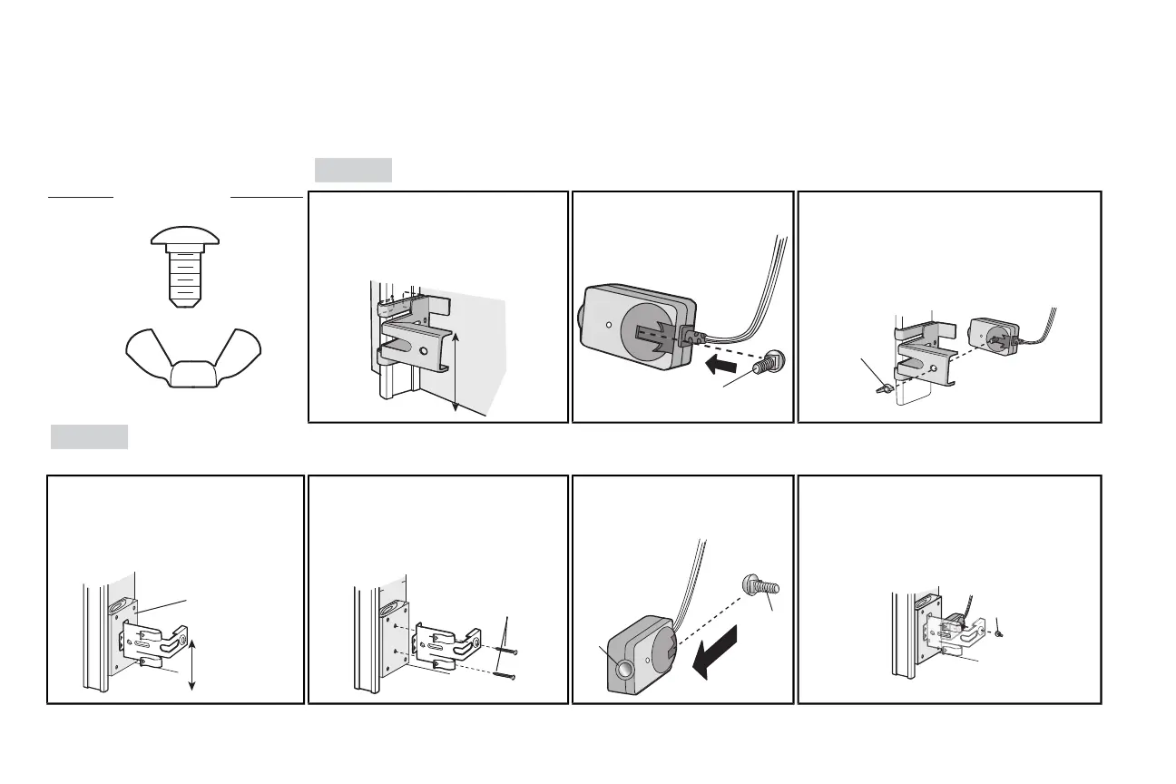
1 Install the Safety Reversing Sensors
The safetyreversing sensors can be attached to the door track,the wall, or the floor. The sensors should be no more than 6 inches (15 cm) above the floor. Ifthe door track will not support the sensor
bracketa wall installation is recommended.Choose one ofthe following installations.
HARDWARE
H17 (2)
Carriage Bolt
1/4"-20x1/2"
H18 (2)
Wing Nut
1/4"-20
OPTION A
DOOR TRACK INSTALLATION
1.1A Slide the curved arms ofthe sensor
bracketaround the edge ofthe door
track.Snap into place so thatthe
sensor bracketis flush against the
track.
no more
than
6 inches
(15 cm)
1.2A Slide the carriage bolt(H17)
into the sloton each sensor.
1.3A Insert the bolt through the hole in the sensor
bracketand attach with the wing nut (H18). The
lenses on both sensorsshould pointtoward
each other. Make sure the lensis not obstructed
by the sensor bracket.
OPTION B WALLINSTALLATION
If additional clearance isneeded an extension bracket (not provided) or wood blockscan be used. Make sure each bracket has the same amount of clearance so they will align correctly.
1.1B Position the sensor bracketagainstthe
wall with the curved arms facing the
door.Make sure there is enough
clearance for the beam to be
unobstructed. Mark holes.
(not provided)
no more
than
6 inches
(15 cm)
1.2B Drill 3/16 inch pilot holes for each
sensor bracketand attach the sensor
brackets to the wall using lag screws
(notprovided).
In
side
G
a
rage
Wa
l
(not provided)
1.3B Slide the carriage bolt(H17) into
the sloton each sensor.
1.4B
Insert the boltthrough the hole in the sensor
bracketand attach with the wing nut (H18). The
lenses on both sensorsshould pointtoward
each other. Make sure the lensis not
obstructed by the sensor bracket.
24
 Loading...