SR113 Family
List of Figures
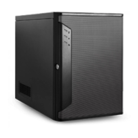
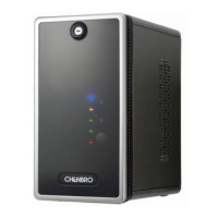
Figure 1 SR113 Tower ....................................................................................................................................... 8
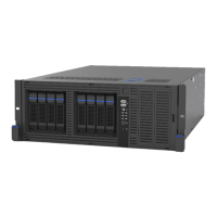
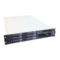
Figure 2 SR113 4U Rackmount ......................................................................................................................... 8
Figure 3 SR113 Side View ................................................................................................................................. 9
Figure 4 SR113 Front view ................................................................................................................................ 9
Figure 5 SR113 11-slot with redundant PSU .................................................................................................. 10
Figure 6 SR113 8-slot with redundant PSU .................................................................................................... 10
Figure 7 SR113 8-slot with single PS2 ............................................................................................................ 10
Figure 8 Front bezel with key lock for system security .................................................................................. 11
Figure 9 Intrusion switch ................................................................................................................................ 11
Figure 10 Front control panel ......................................................................................................................... 12
Figure 11 External 4-Bay and Internal 4-Bay 3.5” HDD .................................................................................. 12
Figure 12 External 8-Bay 3.5" HDD ................................................................................................................. 12
Figure 13 External 8-Bay 3.5" and 8-Bay 2.5" Storage kit .............................................................................. 12
Figure 14 Chassis dimensions ......................................................................................................................... 13
Figure 15 Chassis components ....................................................................................................................... 13
Figure 16 Side cover installation .................................................................................................................... 16
Figure 17 Bezel door removal/installation ..................................................................................................... 17
Figure 18 Remove/install the front panel ...................................................................................................... 18
Figure 19 Front control panel maintenance ................................................................................................... 19
Figure 20 3.5" Device installation................................................................................................................... 19
Figure 21 Guide pin location on storage kit ................................................................................................... 20
Figure 22 Storage kit installation .................................................................................................................... 20
Figure 23 4-Bay 3.5" hot-swap HDD module installation ............................................................................... 21
Figure 24 3.5" HDD tray removal ................................................................................................................... 21
Figure 25 3.5" HDD tray installation ............................................................................................................... 22
Figure 26 3.5" HDD installation (tool-less type) ............................................................................................. 22
Figure 27 3.5" HDD installation (screw type) ................................................................................................. 23
Figure 28 2.5" HDD installation (screw type) ................................................................................................. 23
Figure 29 Middle fan maintenance ................................................................................................................ 24
Figure 30 Fan board maintenance ................................................................................................................. 25
Figure 31 Rear fan kit installation .................................................................................................................. 26
Figure 32 External GPU fan module ............................................................................................................... 27
Figure 33 External GPU fan module installation ............................................................................................ 28
Figure 34 PCIe card retainer installation ........................................................................................................ 29
Figure 35 Card retainer's guide pin ................................................................................................................ 29
Figure 36 GPU card fix bracket installation .................................................................................................... 30
Figure 37 Single PSU installation .................................................................................................................... 31
Figure 38 Redundant PSU removal/installation ............................................................................................. 32
Figure 39 Removal power distribution board ................................................................................................ 32
 Loading...