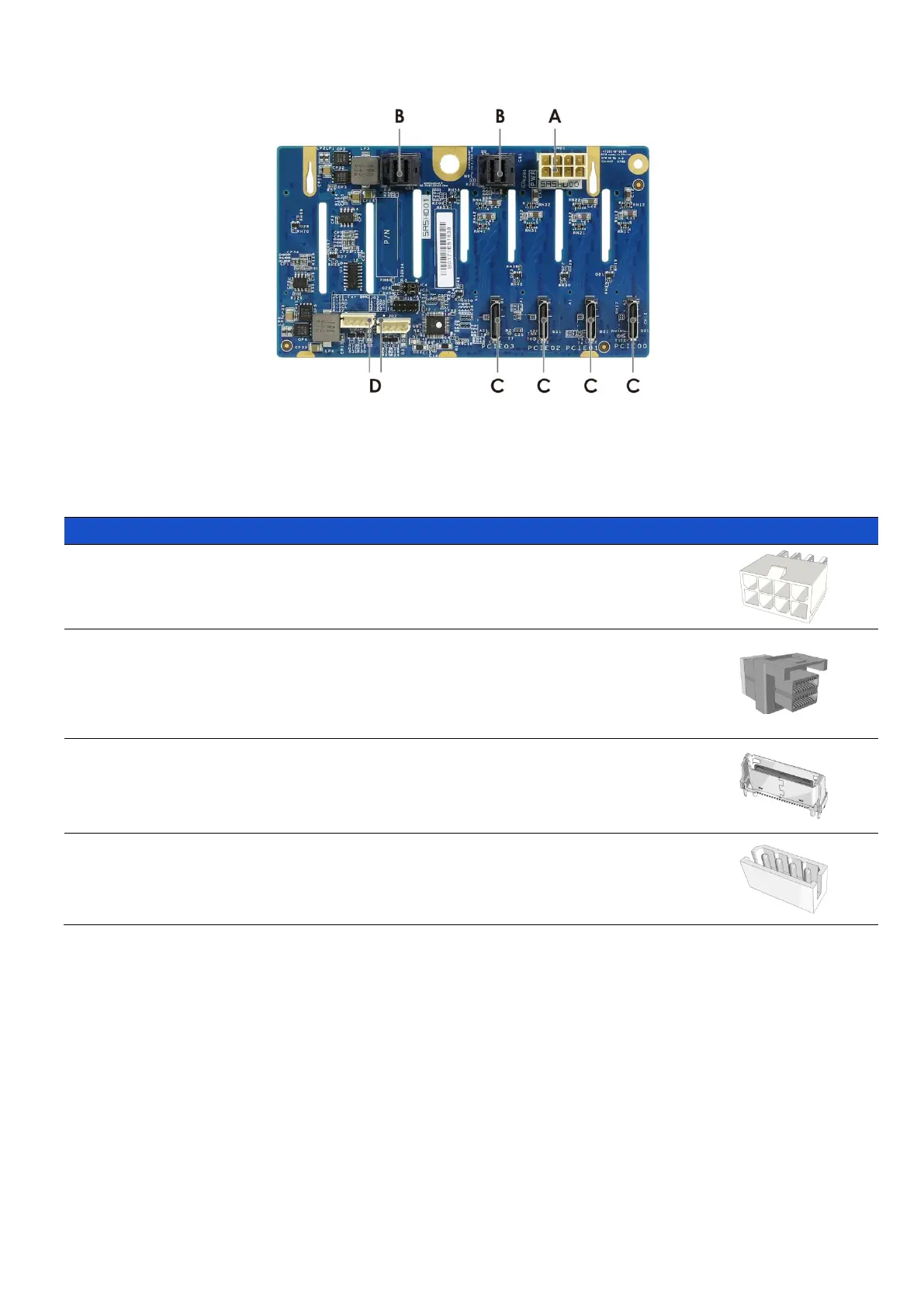
Figure 49 Backplane rear view
Table 10 Connector and pin header function description
The backplane includes one 2 x 4 connector
supplying 12V power to the backplane. Power is
routed to the backplane via a power cable harness
from the power supply.
The backplane includes two multi-ports Mini-SAS
HD connectors providing data signals for eight
SATA/SAS drives on the backplane. A cable can be
routed from matching connectors on the server
board or add-in SATA/SAS HBA cards.
The backplane includes four OCuLink connectors
providing data signals for four NVMe drives on the
backplane. A cable can be routed from matching
connectors on the server board or add-in switch
cards.
The backplane includes two 4-pin connectors. One is
used for LED signal transmission and the other is for
thermal sensor monitoring to MB.
 Loading...