NVF5 Series User Manual Appendix A RS485-MODBUS
Communication Instructions
Group number mapping of the inverter function parameter is the upper bytes of
Modbus register address (0~F corresponding values are 0x00~0x0F); Group Index
(parameter number in the group) mapping is the lower bytes of Modbus register address
(00~99 corresponding values are 0x00~0x63). When data is only required to be stored in
RAM (i.e.,data not stored on power-down), the highest position of the address is “1”.
For example
The corresponding register address of Parameter“F5.27”is“0x051B”
:
1
)
Corresponding address is “0x851B”when data only be stored to RAM.
2
)
Corresponding address is “0x051B”when data only be stored to
EEPROM(Data stored on power-down).
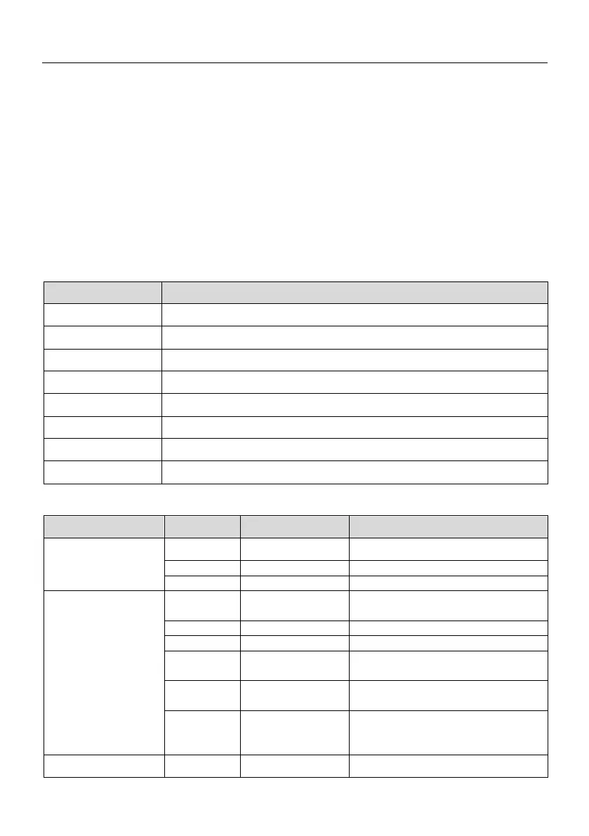
A.5.3 Obtain the parameter attribute of the inverter function code
Parameter attribute of the inverter function code can be obtained by 0x04 command
code. Attribute definition format is shown in Table A.2.。
Table A.2 Data format definition when reading parameter attribute
Maximum value (upper byte)
Maximum value (lower byte)
Minimum value (upper byte)
Minimum value (lower byte)
Current value (upper byte)
Current value (lower byte)
Parameter attribute value (upper byte); refer to Table A.3
Parameter attribute value (lower byte); refer to Table A.3
Table A.3 Definitions of parameter attribute value (bit)
Bit Definition Bit Value Decimal Value Explanation
15~14bit: Display
Type
00 0 Decimal
13~11bit: Modify
Attribute
000 0
Writable and readable at any
time
Modifiable in the stop state
011 3
Writable and readable with an
enterprise password
100 4
Readable with an enterprise
password
101 5
Writable and readable with an
user
10~8bit: Data
000 0 8-bit unsigned bit data type
- 104 -