NVF5 Series User Manual Chapter 3 Installation and Wiring
(2) Three-Phase 380V series(NVF5-0.4/TS4-B~7.5/TS4-B)
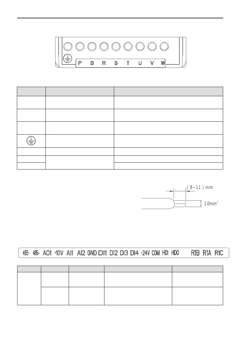
Figure 3-5-2 Power Terminals NVF5-0.4/TS4-B~7.5/TS4-B
Table 3.2 Power Terminals Descriptions
Terminal Name Function Description
R、S、T
Main Power Supply Input
The three-phase AC input
terminals ,connecting with the power grid
L1、L2
Main Power Supply Input
The Single-Phase AC input
terminals ,connecting with the power grid
U、V、W
Inverter Output
The three-phase AC output
terminals ,connecting with the AC motor
Grounding
Grounding terminals,ensure reliable
Single phase type DC+ and DC-
Outer Brake Resistor
Three phase type brake resistor terminals
Single phase type brake resistor terminals
3.5.2 I/O Terminals Descriptions
The control cable of the I/O terminals
should be 1mm2, the requirement of stripping
the control cable is(8~11)mm(Shown as
Figure 3-5-2), the cable core should be fully
contacted with the terminals,the bare cable core
should not be outside of the terminals,or short
circuit will be occurred between cable core. Figure 3-5-2 Requirement of Stripping
the Control Cable
Table 3.3 I/O Terminals Function
Power
Supply
+10V
+10V Power
Supply
Supply
+
10V Power
Output Current
Max.5mA
GND
Supply
Analog Signal and
+
10V
Power Supply Grounding
- 19 -