NVF5 Series User Manual Chapter 6 Parameter Function Description
1 : Torque
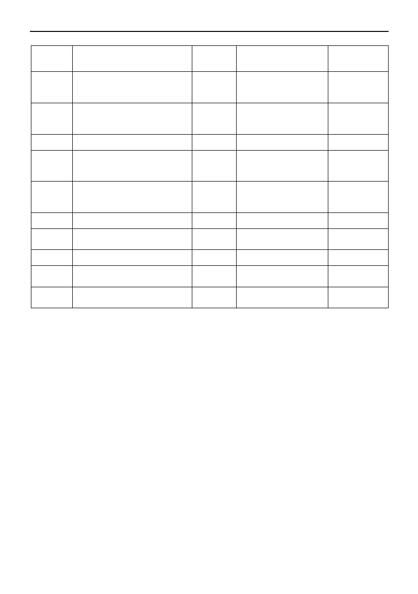
F3.01
Speed Loop Kp 1 ( Low
Speed ASR1-P)
30
1 ~ 100
-
F3.02
Speed Loop Ki Time 1(Low
Speed ASR1-I)
0.50s
(0.01 ~ 10.00) s
-
F3.03
5.00Hz
0 Hz ~ F3.06
-
F3.04
Speed Loop Kp 2 ( Low
Speed ASR2-P)
20
1 ~ 100
-
F3.05
Speed Loop Ki Time 2(Low
Speed ASR2-I)
1.00s
(0.01 ~ 10.00) s
-
F3.06
10.00Hz
F3.03 ~ F0.07
-
F3.07
Slip Compensation Rate in
Vector Control Mode
100%
( 50 ~ 200 ) %
-
F3.08
0.000s
(0.000~0.100)s
-
F3.09
Torque Upper Limit Value
of the Speed Loop
180.0%
(0.0 ~ 300.0) %
-
F3.10
Braking Torque Upper Limit
Value of the Speed Loo
180.0%
(0.0 ~ 300.0) %
-
● Speed Loop PI Switch
The speed loop PI parameters are divided into two groups: low speed and high speed,
when the running frequency is smaller than F3.03-Switch Frequency1,speed loop PI
regulated parameters are F3.01 and F3.02,when the running frequency is greater than
F3.06-Switch Frequency2 ,speed loop PI regulated parameters are F3.04 and F3.05.
The speed loop dynamic response characteristics of vector control can be adjusted by
setting the proportion and integration time of the speed regulator. Increasing proportional
gain and reducing integration time can speed up the dynamic response of speed loop.
However, if the gain is too large or the integration time is too small, the system will
oscillate.
- 68 -