Freeze-dryer Alpha 1-4 LDplus
Freeze-dryer Alpha 2-4 LDplus
2 Layout and mode of operation
Version 11/2006, Rev. 2.2 of 17/10/2016 • sb
Translation of the original operating manual
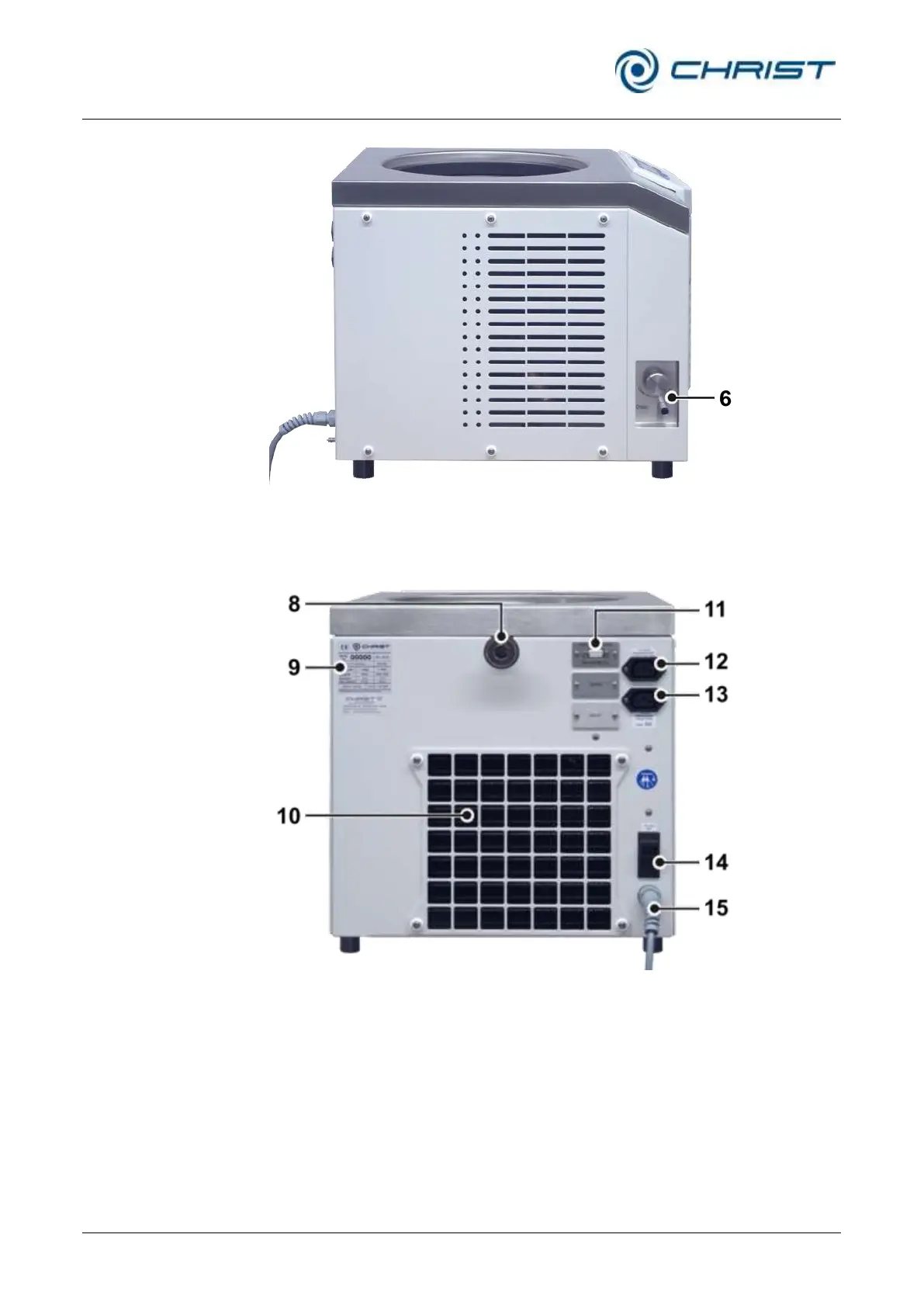
6 Equipotential bonding
screw
7 Aeration and media
drain valve
Fig. 3: Left side of the freeze-dryer
8 Vacuum connection
9 Name plate (see
chapter 2.1.2 - "Name
plate")
10 Heat exchanger of the
refrigeration unit
11 Electrical connection of
the vacuum sensor
12 Power supply of the
pressure control valve
13 Power supply of the
vacuum pump
14 Mains fuse
15 Mains cable
Fig. 4: Rear view of the freeze-dryer
Pos: 20 /010 Uni versalmodule/S eitenwechsel @ 0\mod_120 2116244312_ 0.docx @ 105 @ @ 1