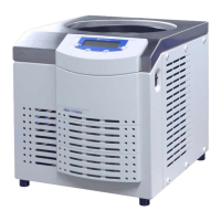
Freeze-dryer Alpha 1-4 LDplus
Freeze-dryer Alpha 2-4 LDplus
Version 11/2006, Rev. 2.2 of 17/10/2016 • sb
Translation of the original operating manual
Pos: 93 /200 Chri st/360 GT-BA Labor-Pilot (ST ANDARDMODU LE)/050 A ufstellung und Anschl uss/050-00 20 Energievers orgung--------------------------------------- @ 25\mod_1404983 740008_68.d ocx @ 183537 @ 2 @ 1
5.2 Power supply
Pos: 94 /200 Chri st/361 GT-BA Labor-Pilot (PR OJEKTE)/Al pha/Alpha 1-4 _2-4 LDplus/050 A ufstellung und Anschluss/050- 0020-0010 Anschlussart Alp ha 1-4_2-4 LDplus @ 35\ mod_14303800902 36_68.docx @ 258823 @ 3 @ 1
5.2.1 Connection
The operating voltage on the name plate must correspond to the local
supply voltage
CHRIST freeze-dryers are units of safety class I.
Alpha 1-4 LDplus and Alpha 2-4 LDplus units have a three-wire power
cord with a fixed cable(see chapter 10 - "Technical data").
An equipotential bonding screw is located on the back below the mains
power input (see chapter 2.1.1 - "Functional and operating elements"). This
equipotential bonding screw can be used to perform an earth conductor
check.
Pos: 95 /010 Uni versalmodule/ Leerzeile @ 0\mod_120 2116244500_ 0.docx @ 11 4 @ @ 1
Pos: 96 /200 Chri st/360 GT-BA Labor-Pilot (ST ANDARDMODU LE)/050 A ufstellung und Anschl uss/050-00 20-0020 Sich erungen bauseits @ 25\mod _140498374101 5_68.docx @ 18 3551 @ 3 @ 1
5.2.2 Customer-provided fuses
Typically, the freeze-dryer must be protected with 16 Amp G fuses that are
to be provided by the customer.
Pos: 97 /010 Uni versalmodule/ Leerzeile @ 0\mod_120 2116244500_ 0.docx @ 11 4 @ @ 1
Pos: 98 /010 Uni versalmodule/ Leerzeile @ 0\mod_120 2116244500_ 0.docx @ 11 4 @ @ 1
Pos: 99 /200 Chri st/361 GT-BA Labor-Pilot (PR OJEKTE)/Al pha/Alpha 1-4 _2-4 LDplus/050 A ufstellung und Anschluss/050- 0030 Belüft ungs- und Me dienablaufventil Alpha 1-4_2- 4 LDplus @ 35\mo d_143072804 4599_68.docx @ 259092 @ 2 @ 1
5.3 Aeration and media drain valve
The aeration and media drain valve is located on the left side of the unit
(see chapter 2.1.1 - "Functional and operating elements").
After the end of a freeze-drying process, the unit will be aerated via the
aeration valve.
Additionally, it is used to drain off the condensate and the defrosting water.
• Connect the drain hose (included in the scope of supply) to the hose
connector.
• Place a collecting vessel under the unit.
The hose must be laid with a continuous slope and the end of the hose
must always be above the liquid level in the collecting vessel. This prevents
water and dirt residues from being sucked into the ice condenser chamber
if there is negative pressure when the media drain valve is opened.
The ice condenser chamber can be flooded with nitrogen via the hose
nozzle of the aeration valve.
Pos: 100 /010 Uni versalmodule/ Seitenwechsel @ 0\mod_12 02116244312 _0.docx @ 105 @ @ 1