Digital Power Meter 66203/66204 User’s Manual
4-10
The frequency measurement detects the input voltage signal frequency. It is a computed
average value after captured the input voltage signal within a time interval. The measured
voltage frequency can also be the base of current measurement time.
When measuring the AC voltage frequency, the input signal voltage amplitude should be
10% or above over the range as the hysteresis comparator circuit will detect the input
voltage’s zero-crossing. The filter design before the hysteresis comparator circuit can help
filtering out the noise on the input signal. However, if the noise peak is too big that cannot
be processed by the filter, it could cause frequency measurement error or affect the AC
measurement accuracy.
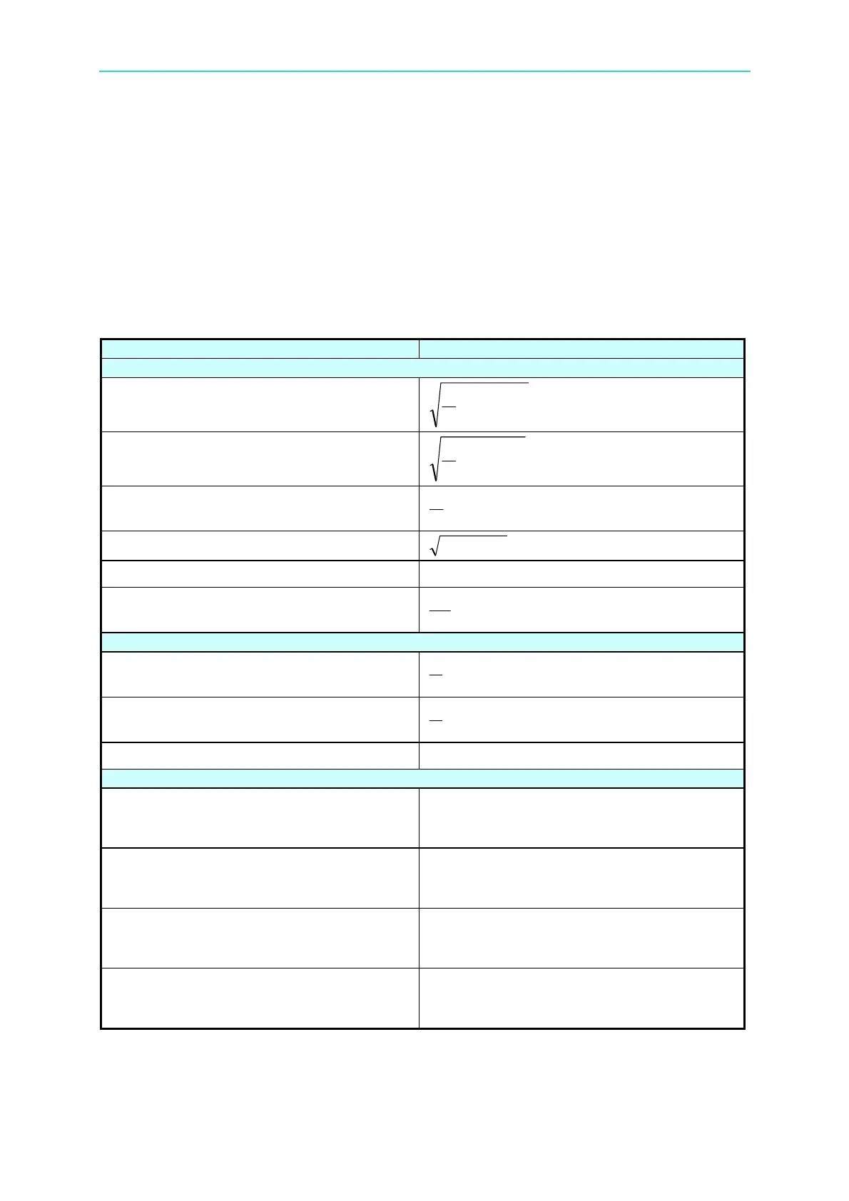
Single Phase Measurement Parameter
Measurement Parameter Computing Equation
True rms value
rms
V
∫
T
dt
t
v
T
0
2
)(
1
rms
I
∫
T
dt
t
i
T
0
2
)(
1
W
∫
T
dttitv
T
0
)()(
1
VAR
22
WVA −
VA
rmsrms
IV
P
VA
W
Mean value
dc
V
∫
T
dttv
T
0
)(
1
dc
I
∫
T
dtti
T
0
)(
1
dc
W
dcdc
IV
Peak value
+PK
V
The maximum sampling value of the positive
half wave of
)(tv
during two continuous
cycles.
−PK
V
Absolute value of the maximum sampling
value of the negative half wave of
)(tv
during two continuous cycles.
+PK
I
The maximum sampling value of the positive
half wave of
)(ti during two continuous
cycles.
−PK
I
Absolute value of the maximum value of the
negative half wave of
)(ti during two
continuous cycles.
 Loading...


