4
Preparing to Install or Remove
Options Modules
Before removing the instrument from its hous-
ing, ensure that all power has been removed
from the rear terminals. Any repair or modi-
fication done on the controller is subject to
the requirements of the jurisdiction. The ju-
risdiction can be defined as plant safety or
chief engineer, city, county or state electrical
inspector, etc. Modules / boards should only
be replaced by a trained and qualified techni-
cian per the latest edition of the NEC (National
Electric Code).
1. Remove the instrument from its housing by grip-
ping the side edges of the front panel (there is a
finger grip on each edge) and pull the instrument
forwards. This will release the instrument from the
rear connectors in the housing and will give access
to the PCBs.
2. Take note of the orientation of the instrument for
subsequent replacement into the housing. The po-
sitions of the main and option PCBs in the instru-
ment are shown below.
Removing/Replacing Option Modules
(“Output” & “Option” are interchangeable
terms)
With the instrument removed from its housing:
1. To remove or replace modules into Option Slots 1,
A or B, it is necessary to gently separate the CPU
and PSU PCBs. This is achieved by detaching the
main boards (PSU and CPU) from the front mold-
ing by lifting first the upper and then lower mount-
ing struts as shown. This frees the boards from the
front. If only Option slots 2 or 3 are to be changed,
this stage is not required as these slots are acces-
sible without separating the main boards from the
front.
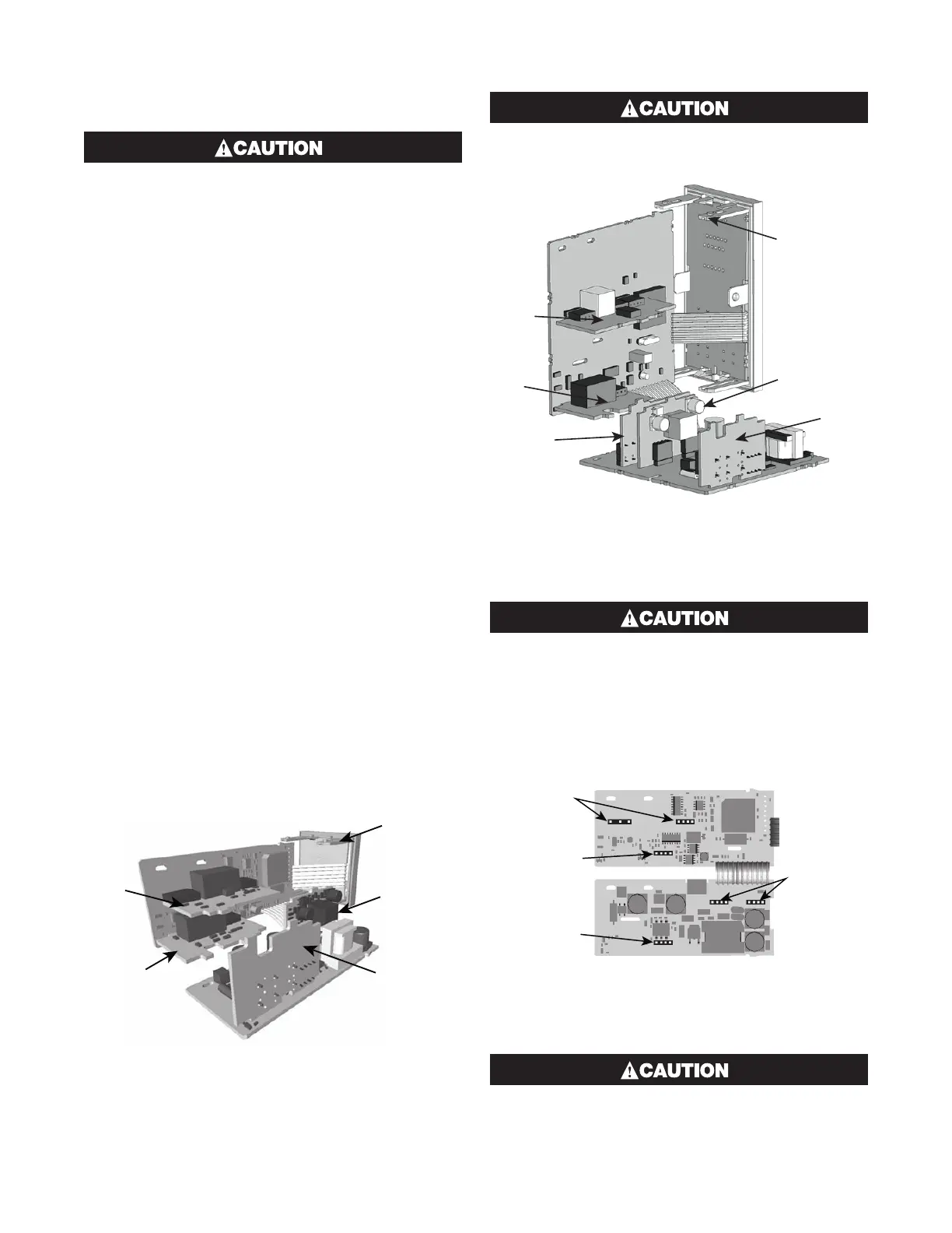
Figure 5
Location of Option Modules - 1/16 DIN Instruments
Option
Slot 2
Option Slot 3
Option
Slot A
n
Struts
Take care not to put undue stress on the ribbon
cable attaching the display and CPU boards.
Figure 6
Location of Option Modules
1/8 & 1/4 DIN Instruments
Option
Sl
ot 2
Option
Slot A
Option
Slot B
Slot 3
Option
Slot 1
Mounting
Struts
Take care not to put undue stress on the ribbon
cable attaching the display and CPU boards.
2. Remove or fit the modules into the Option slots as
required. The location of the connectors is shown
below. Tongues on each option module locate into a
slots cut into the main boards, opposite each of the
connectors.
Figure 7
Option Module Connectors
1/16 DIN Instruments
Option Slot 3
Option Slot 2
Option Slot A
Connectors
PL5 & PL6
Option Slot 1
Connectors
PL7 & PL8
Check for correct orientation of the modules
and that all pins locate correctly into the socket.
 Loading...

