14
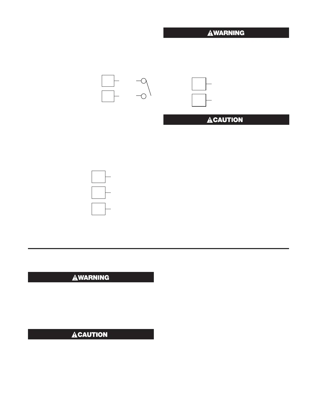
Option Slot B Connections – Digital Input
2 (Full Auxiliary Module)
If option slot B is fitted with the Full Auxiliary input
module (see below), a secondary digital input is also
provided. This may be connected to either the voltage
free contacts of a switch or relay, or a TTL compatible
voltage.
Figure 35
Option Slot B – Digital Input 2 Connections
9
8
_
+
See Option Slot A
for Digital Input
on 1/16 DIN models
1/16 DIN 1/4 DIN & 1/8 DIN
Option Slot B Connections – 1/4 DIN & 1/8
DIN Full Auxiliary Input Module
If option slot B is fitted with full auxiliary input feature,
input connections are as shown.
Figure 36
Option Slot B – Full Auxiliary Input Connections
See Option Slot A for
Aux input (basic type
only) on 1/16 DIN
7
6
5
(or Pot Low)
_
+
(or Pot Wiper)
(or Pot High)
1/16 DIN 1/4 DIN & 1/8 DIN
IF THE FULL AUXILIARY MODULE HAS BEEN
FITTED, THE BASIC AUXILIARY INPUT MUST
NOT BE FITTED INTO OPTION SLOT A.
Current Transformer Connection -
1/16 DIN
7
8
Current Transforme
Use only Chromalox supplied current trans-
formers. Transformers are non-polar devices.
5 Powering Up
ENSURE SAFE WIRING PRACTICES ARE FOL-
LOWED
The instrument must be powered from a supply ac-
cording to the wiring label on the side of the unit. The
supply will be either 100 to 240V AC, or 24/48V AC/DC
powered. Check carefully the supply voltage and con-
nections before applying power.
When powering up for the first time, discon-
nect the output connections.
Powering Up Procedure
At power up, a self-test procedure is automatically
started, during which all LED segments and indicators
are lit. At the first power up from new, or if the option
modules are changed, Goto Conf will be displayed, in-
dicating configuration is required (refer to section 6).
At all other times, the instrument returns to operator
mode once the self-test procedure is complete.
Overview of Front Panel
The illustration below shows a typical instrument front
panel. Refer to the following table – Typical LED func-
tions for a description of the front panel indicators.
Each model in the range will vary slightly from the ex-
ample shown.
Displays
Controllers are provided with a dual line display and
LED indicators for mode, automatic tune, alarm and
output status. The upper display shows the process
variable value during normal operation, whilst the lower
display shows the Setpoint value. See the preceding
diagram - Typical front panel and keys.
 Loading...

