5
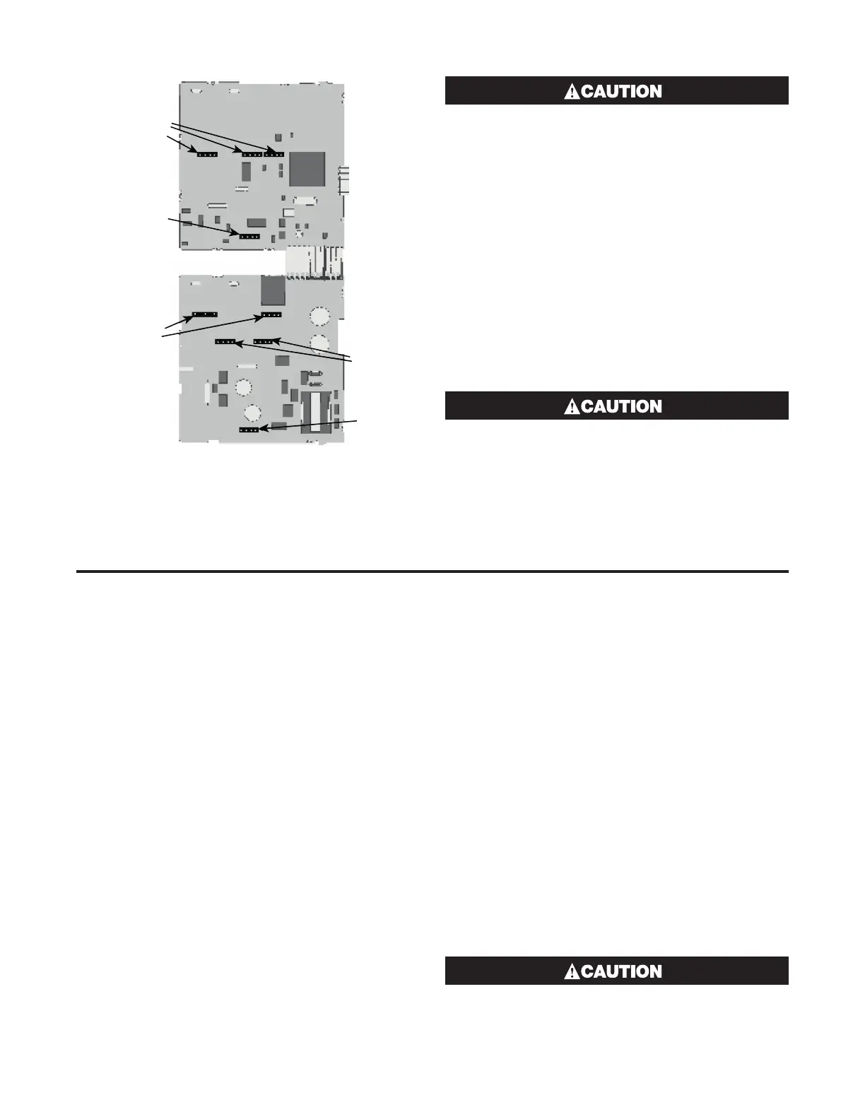
Figure 8
Option Module Connectors
1/8 & 1/4 DIN Instruments
Option Slot 2
Connector PL4A
Option Slot
Connectors
PL5 & PL6
Option Slot B
Connectors PL2A,
PL2B & PL2C
Option Slot
Connectors
PL4B
Option Slot 1
Connectors
PL7 & PL8
Check for correct orientation of the modules
and that all pins locate correctly into the socket.
Replacing the Instrument in its Housing
With the required option modules correctly located
into their respective positions the instrument can be
replaced into its housing as follows:
1. If required, move the CPU and PSU boards back
together, taking care to locate the option module
tongues into the slots in the board opposite. Hold
the main boards together whilst relocating them
back into the mounting struts on the front panel.
2. Align the CPU and PSU PCBs with their guides and
connectors in the housing.
3. Slowly and firmly, push the instrument in position.
Ensure that the instrument is correctly ori-
entated. A mechanical stop will operate if an
attempt is made to insert the instrument in
the wrong orientation, this stop MUST NOT be
over-ridden.
4 Wiring Instructions
Options Modules and Functions
Electrical noise is a phenomenon typical of industrial
environments. As with any instrumentation, these
guidelines should be followed to minimize the effect of
noise.
Installation Considerations
Ignition transformers, arc welders, mechanical contact
relays and solenoids are all common sources of electri-
cal noise in an industrial environment and therefore the
following guidelines MUST be followed.
1. If the instrument is being installed in existing equip-
ment, the wiring in the area should be checked to
ensure that good wiring practices have been fol-
lowed.
2. Noise-generating devices such as those listed
should be mounted in a separate enclosure. If this
is not possible, separate them from the instrument,
by the largest distance possible.
3. If possible, eliminate mechanical contact relays and
replace with solid-state relays. If a mechanical relay
being powered by an output of this instrument can-
not be replaced, a solid-state relay can be used to
isolate the instrument.
4. A separate isolation transformer to feed only the
instrumentation should be considered. The trans-
former can isolate the instrument from noise found
on the AC power input.
AC Power Wiring - Neutral (for 100 to 240V
AC versions)
It is good practice to ensure that the AC neutral is at or
near ground (earth) potential. A proper neutral will help
ensure maximum performance from the instrument.
Wire Isolation
Four voltage levels of input and output wiring may be
used with the unit:
1. Analog input or output (for example thermocouple,
RTD, VDC, mVDC or mADC)
2. Relays & Triac outputs
3. SSR Driver outputs
4. AC power
The only wires that should run together are
those of the same category.
 Loading...

