65
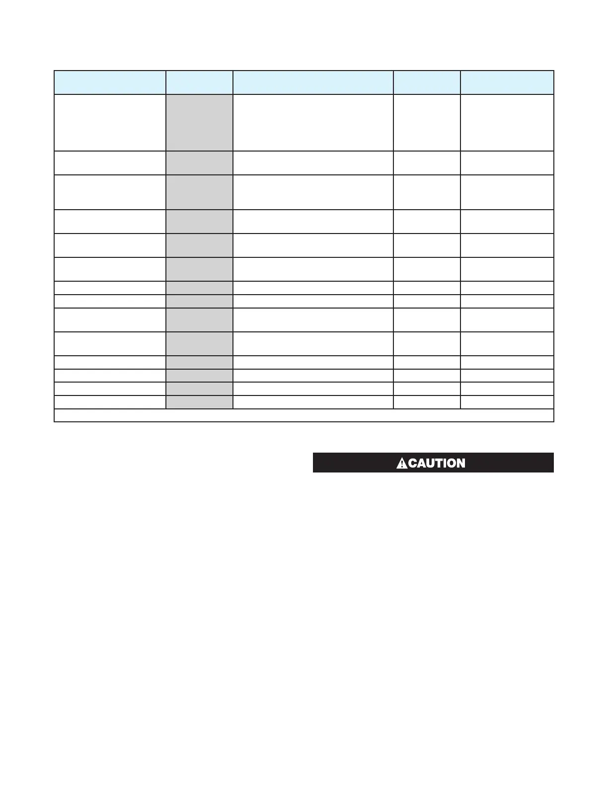
Table 27. 6050 & 4050 Set Up Mode Parameters
Parameter
Lower
Display
Upper Display
Adjustment Range Default Value
When
Visible
Limit Setpoint value
SP
Scaled Range Minimum to Scaled
Range Maximum
Range when
CtrL=Hi
Range Min.
when
CtrL=Lo
Always
Limit Hysteresis
HYST
1 LSD to full span in display units,
on the safe side of the limit SP
1
Always
Input Filter Time
constant
FiLt
OFF, 0.5 to 100.0 secs in 0.5 sec
increments (see CAUTION note at
end of section)
2.0
Always
Process High Alarm 1
value*
PhA 1
Range Min. to Range Max. Range
Max.
ALA1=P
-
Hi
Process Low Alarm 1
value*
PLA 1
Range Min. to Range Max. Range
Min.
ALA1=P
-
Lo
Deviation Alarm 1
Value*
dAL1
±span from setpoint
5 ALA1=de
Band Alarm 1 value*
bAl1
1 LSD to full span from setpoint.
5 ALA1=bAnd
Alarm 1 Hysteresis*
AHY1
Up to 100% of span
1
Always
Process High Alarm 2
value*
PhA2
Range Min. to Range Max. Range
Max.
ALA2=P
-
Hi
Process Low Alarm 2
value*
PLA2
Range Min. to Range Max. Range
Min.
ALA2=P
-
Lo
Deviation Alarm 2 Value
dAL2
±span from setpoint
5 ALA2=dE
Band Alarm 2 value*
bAL2
1 LSD to full span from setpoint.
5 ALA2=bAnd
Alarm 2 Hysteresis*
AHY2
Up to 100% of span
1
Always
Set-up Lock Code
SLoc
0 to 9999
10
Always
**First Operator mode displays follows.
*Note: Alarm parameters marked * are repeated in
Configuration Mode.
**Note: Once the complete list of Set Up Mode pa-
rameters has been displayed, the first Op-
erator Mode display is shown without exiting
from Set Up Mode.
An excessively large filter time could signifi-
cantly delay detection of a limit condition. Set
this value to the minimum required to remove
noise from the process variable.
 Loading...

