20
B. Modbus RTU/RS485, Profibus DP Interface
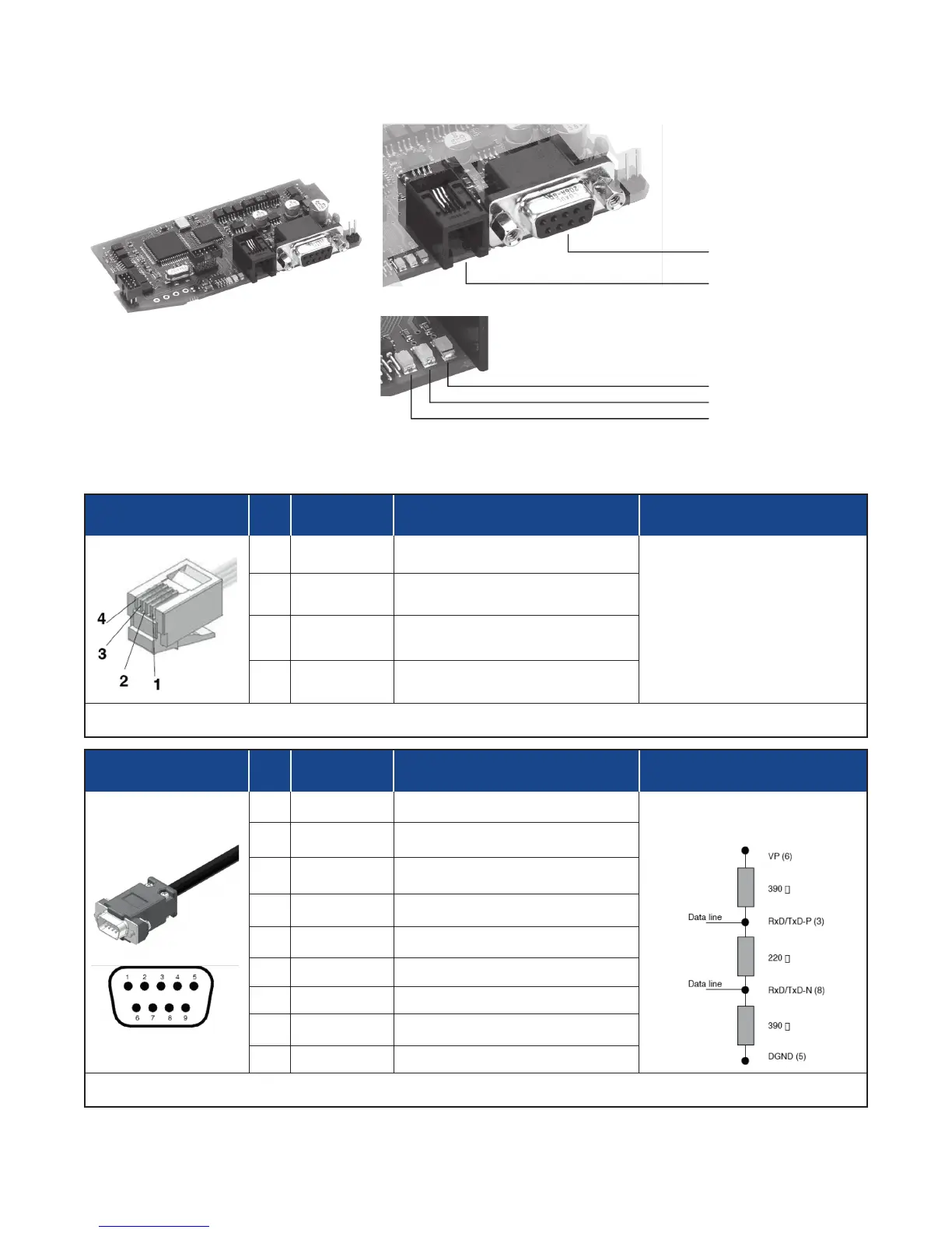
Connector S4
RJ10 4-4 Pin Pin Name Description Note
1 GND1 (**) -
(**) Connect the GND signal to
Modbus devices with a line
distance > 300 ft. (100 m)
2 Rx/Tx+ Data reception/transmission (A+)
3 Rx/Tx- Data reception/transmission (B-)
4 +V Reserved -
Cable Type: Flat telephone cable for pin 4-4 conductor 28 AWG
Connector S5
D-Sub 9 Pins Male Pin Name Description Note
1 Shield EMC Production
Connect the terminal resis-
tances as shown in the figure.
2 M24V Output Voltage - 24V
3 RxD/TxD-P Data reception/transmission
4 n.c. n.c.
5 DGND Data Ground
6 VP Positive Power Supply +5V
7 P24V Output Voltage +24V
8 RxD/TxD-N Data Reception/Transmission
9 n.c. n.c.
Cable Type: Shielded 1 pair 22 AWG conforming to PROFIBUS.
S5 Female DB9 Connector
S4 Fema
Yellow LED
Red LED

 Loading...


