22
D. Modbus RTU/RS485, DeviceNet Interface
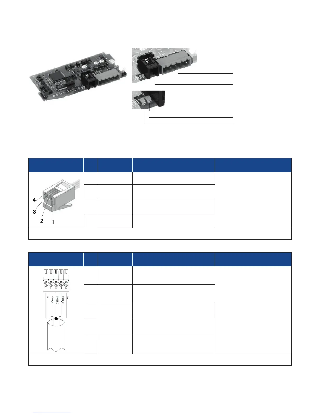
Connector S4
RJ10 4-4 Pin Pin Name Description Note
1 GND1 (**) -
(**) Connect the GND signal to
Modbus devices with a line
distance > 300 ft. (100 m)
2 Rx/Tx+ Data reception/transmission (A+)
3 Rx/Tx- Data reception/transmission (B-)
4 +V Reserved -
Cable Type: Flat telephone cable for pin 4-4 conductor 28 AWG
Connector S5
D-Sub 9 Pins Male Pin Name Description Note
1 V- Negative Power Supply
Connect a 120Ω / 1/4W resis-
tance between the “CAN_L”
and “CAN_H” signals at each
end of the DeviceNet network.
2 CAN_L Low Signal
3 SHIELD Shield
4 CAN_H High Signal
5 V+ Positive Power Supply
Cable Type: Shielded 1 pair 22 AWG conforming to PROFIBUS.
S5 Male Connector
S4 Female RJ10 Connector
Red LED
Green LED
 Loading...


