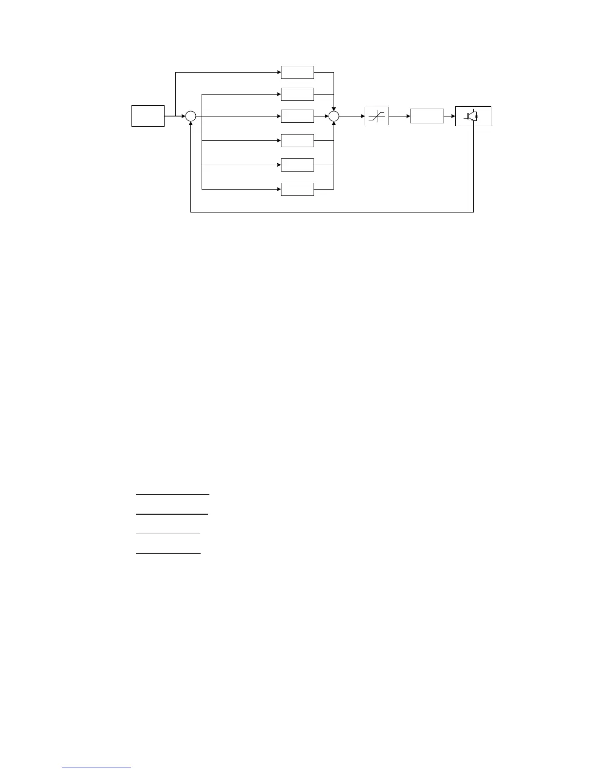
Therefore, the main characteristics of the Resonant Control applied are the ones listed below:
- Control loop rate of 15 kHz.
- 15 harmonics controlled*: 1
st
-15
th
- 15 control loops executed per phase.
- 45 control loops executed in total (for the 3 phases).
- Each control loop controls independently magnitude and angle of one harmonic.
- Any kind of load can be implemented in the EUT side.
- All harmonics can be suppressed in the grid side.
* It should be noted that the equipment bandwidth is 800 Hz. Therefore, the harmonic content
will be determined by the bandwidth as well as by the fundamental frequency specified by the
user.
Finally, the following pictures are some examples of how the EL Resonant Control can work. It is
important to take into account that, in these three pictures:
- Yellow waveform: input U
phase-N
- Green waveform: input I
phase-N
- Pink waveform: output U
phase-N
- Blue waveform: output I
phase-N