3.6.- STARTING UP THE DEVICE
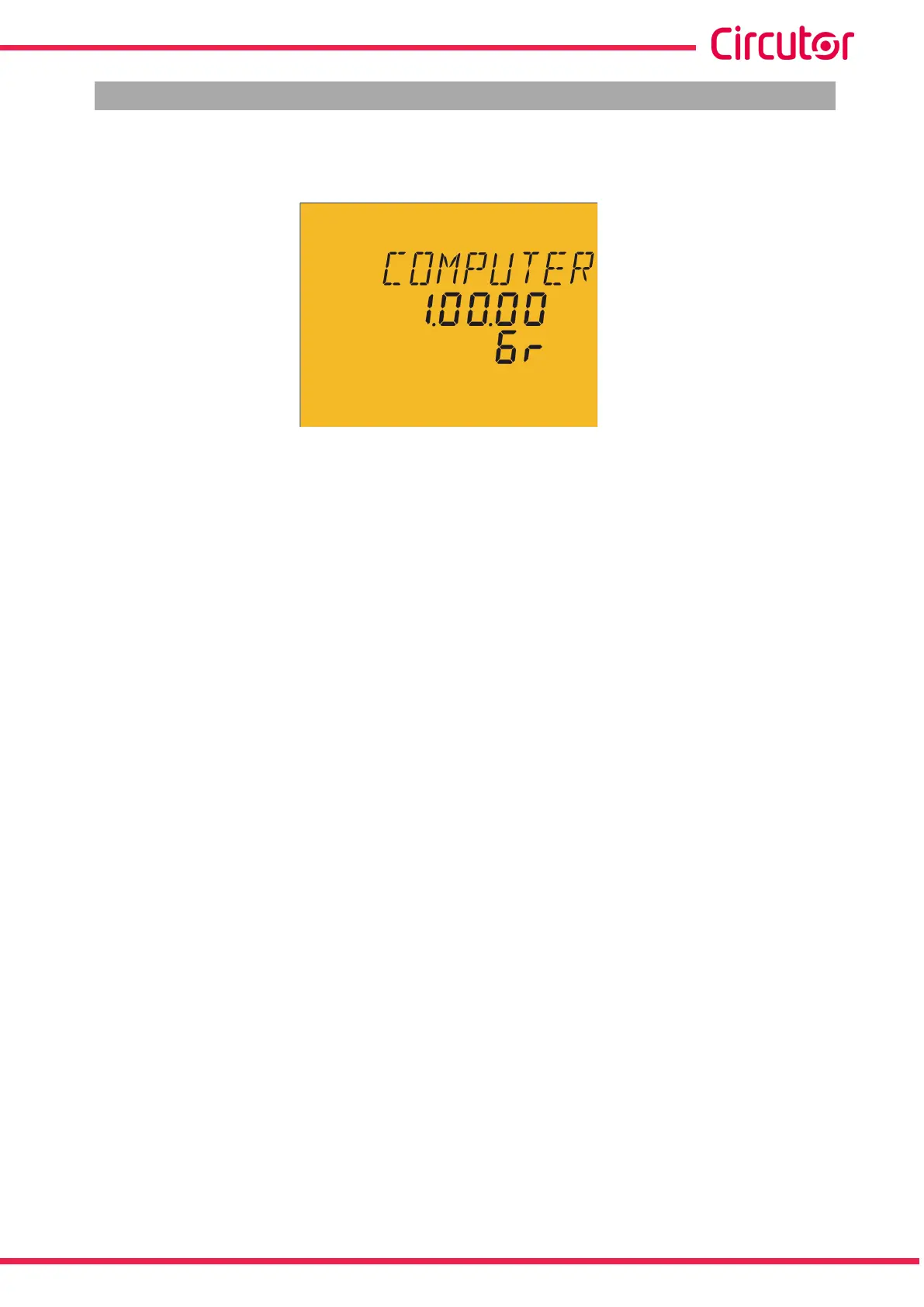
Once the Computer SMART III is powered on, the following screen appears on the display, Figure 13,
which shows the name of the device, the version and the model.
Figure 13: Computer SMART III home screen.
After a few seconds, the main measurement screen appears.
23
Instruction Manual
Computer SMART III