2-5
Cisco 10000 Series Router Troubleshooting Guide
OL-0439-02
Chapter 2 PEM Faults and Blower Failures
Blower Module Faults
Blower Module Faults
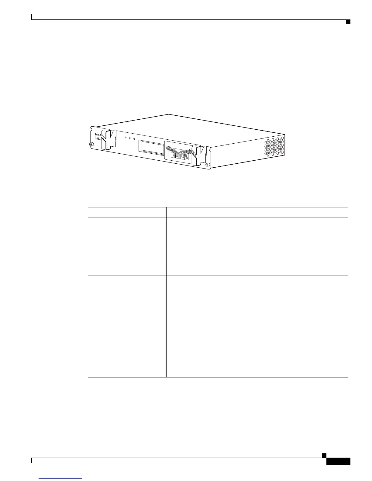
The blower module is critical to the operation of the Cisco 10000 series router. Severe overheating can
result in system failure. The blower module contains a redundant array of fans in a single shelf unit.
Figure 2-3 shows the blower module front panel and its LED indicators.
Figure 2-3 Blower Module
Table 2-5 lists the blower module fault indications and recommended actions.
30002
FANS
OK
FAN
FAILURE
MULTI-
FAN
FAILURE
W
hen
hot swap
p
ing
this fan
tra
y,
re
m
o
val an
d
rep
lacem
ent m
us
t
b
e
don
e
in un
de
r tw
o m
inutes
or
system
shu
tdo
w
n w
ill o
ccu
r.
C
A
U
T
IO
N
Table 2-5 Blower Module Fault Indications and Recommended Action
Symptom Steps to Take
Fans OK LED on blower
module fails to power on
1. Make sure the blower module is fully inserted into the chassis.
2. If you use DC PEMs, make sure the wiring is not reversed.
3. Replace the blower module.
FAN FAILURE LED is lit Replace the blower module.
MULTI-FAN FAILURE
LED is lit
Replace the blower module.
Fans run but the system
overheats
1. Make sure that all intake and exhaust vents on the front and rear
of the chassis are free of blockages.
2. Make sure that the ambient temperature and other environmental
factors in the system area are within the ranges specified in the
“Using the show environment Command for Basic
Troubleshooting” section on page 1-3.
3. Make sure all line cards and blank faceplates are in place. The
cooling system cannot operate effectively unless the chassis is
fully enclosed.
4. Check the air filter, and if necessary clean or replace it.
5. Reduce the ambient temperature of the area surrounding the router
chassis.
 Loading...


