6-2
Cisco 10000 Series Router Troubleshooting Guide
OL-0439-02
Chapter 6 Troubleshooting Serial Lines
Optical Signal Input/Output Problems
Evaluating the Power Budget
Use the following equation to ensure that an appropriate power budget has been allotted to optical links
terminating at the Cisco 10000 series router.
The power budget (PB) is the maximum possible amount of power transmitted. The following equation
shows the calculation of the power budget:
PB = PTmin – PRmin
Where:
PTmin = Minimum transmitter power
PRmin = Minimum receiver sensitivity
Insufficient power budget occurs when the power margin (PM) is less than 0. PM is equal to the power
budget minus the link loss (LL).
PM = PB – LL
Three factors contribute to link loss:
• Fiber attenuation (single mode) 0.5 dB/km
• Connector 0.5 dB
• Splice 0.5 dB
Note These are typical values; refer to the manufacturer for the actual values.
Managing Receiver Overload
Receiver overload can occur when (PR
max
– (PT
max
– LL)) is less than 0, where PRmax is maximum
receiver power and PT
max
is maximum transmitter power. To prevent overloading the receiver, you can
use an attenuator on the link between any singlemode SONET transmitter and the receiver. Doing so
increases the value of LL.
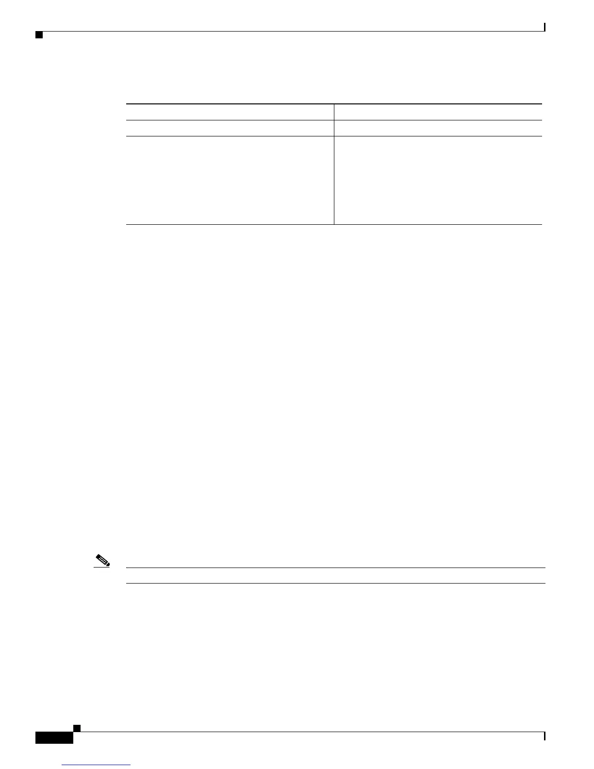
Table 6-1 Optical Fiber Types for Cisco 10000 Series Router Line Cards
Card Type Appropriate Fiber Type
OC-12 Packet Over SONET line card Single mode.
Gigabit Ethernet line card The appropriate fiber type for the gigabit Ethernet
line card is dependent upon the installed GBIC.
1. 1000BaseSX, multimode.
2. 1000BaseLX/LH, single mode and
multimode
1
.
3. 1000BaseZX, single mode.
1. Mode-conditioning patch cord (CAB-GELX-625 or equivalent) is required. If you use an ordinary patch cord with MMF,
1000BaseLX/LH GBICs, and a short link distance (10s of meters), you can cause transceiver saturation, resulting in an
elevated bit error rate (BER). In addition, if you use the LX/LH GBIC with 62.5-micron diameter MMF, you must install a
mode-conditioning patch cord between the GBIC and the MMF cable on both the transmit and receive ends of the link. The
mode-conditioning patch cord is required for link distances greater than 984 ft. (300 m).
 Loading...


