21
Start the Cisco ASR 1004 Router
After installing your Cisco ASR 1004 Router and connecting cables, start the router as follows.
Step 1 Check for the following:
–
Make certain that each shared port adapter is firmly seated in its subslot and its captive screws are securely tightened.
–
The Cisco ASR1000-ESP10, Cisco ASR1000-ESP20, and Cisco ASR1000-ESP40 forwarding processor in the Cisco
ASR 1004 router is inserted in slot F0, is firmly seated in its slot, and its captive screws are securely tightened.
–
All network interface cables are connected.
–
The console terminal is turned on.
Step 2 Turn on power. The green OK LED on the power supply turns on.
Step 3 Listen for the fans; you should immediately hear them operating.
Step 4 During the boot process, observe the power LEDs. The power LED should be green on all boards. The Status LED lights
yellow to indicate booting and then green when IOS is running.
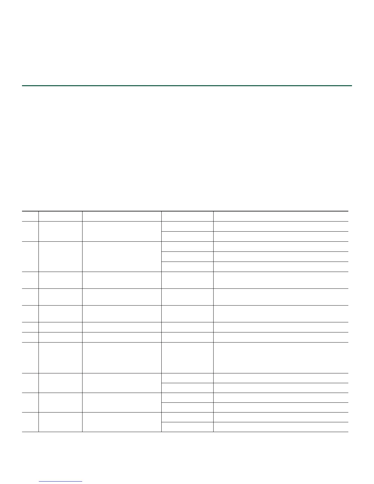
Table 1 provides information about the LEDs as the system starts.
Table 1 Cisco ASR 1004 Router LED Activity
No. LED Label LED Color In the Power Up State -Behavior Description
1
PWR Power Solid green All power requirements are within specification
Off Off, the router is in standby mode.
2
STAT System status Solid green Cisco IOS has successfully booted.
Yellow BOOT ROM has successfully loaded.
Red System failure.
3
ACTV Active Green Lit when this is the active route processor
(ASR1000-RP1 or Cisco ASR1000-RP2).
4
STBY Standby Yellow Lit when this is the standby ASR 1000 Series route
processor.
5
CRIT Critical Solid Red Critical alarm indicator. This is on at power up,
turned off by software.
6
MAJ Major Solid Red Major alarm indicator.
7
MIN Minor Amber Minor alarm indicator.
8
ACO One Alarm cutoff switch. Button When you press this button an interrupt is
generated informing software that the audible
alarm relays will be disabled. This interrupt
generates to both processors.
9
DISK HD Internal Hard Drive LED Flashing Green Activity indicator.
Off No activity.
10
DISK USB External Compact FLASH
LED
Flashing Green Activity indicator.
Off No activity.
11
DISK BF Internal Compact FLASH
(BootDisk) LED
Flashing Green Activity indicator.
Off No activity.
 Loading...


