12
Step 5 Locate the chassis ground connector on the side of your chassis.
Step 6 Insert the two screws through the holes in the grounding lug.
Step 7 Use the Number 2 Phillips screwdriver to carefully tighten the screws until the grounding lug is held firmly to the
chassis. Do not overtighten the screws.
Step 8 Connect the opposite end of the grounding wire to the appropriate grounding point at your site to ensure an adequate
chassis ground.
This completes the procedure for attaching a chassis ground connection. Go to the “Connect the Router to the Network” section
on page 12 for information on attaching cables.
4 Connect the Router to the Network
This section provides information about cables and ports and attaching the router to the network.
• Console and Auxiliary Port Cable Connections, page 12
• Management Ethernet Port Cable Connection, page 13
• Connect the Shared Port Adapter Cables, page 14
• Install Cables in the Cable-Management Bracket, page 14
Console and Auxiliary Port Cable Connections
This section describes how to attach a cable to the console or auxiliary ports on the Cisco ASR 1004 Router. The Cisco ASR1004
Router uses RJ-45 ports for both the auxiliary port and console port to attach a modem or console terminal.
The console DCE-mode port connects a console terminal and a DTE-mode auxiliary port connects a modem or other DCE device
to your router.
Note Both the console and the auxiliary ports are asynchronous serial ports; any devices connected to these ports must be
capable of asynchronous transmission. (Asynchronous is the most common type of serial device; for example, most
modems are asynchronous devices.)
Step 1 Before connecting a terminal to the console port, configure the terminal to match the router console port as follows:
9600 baud, 8 data bits, no parity, 1 stop bits.
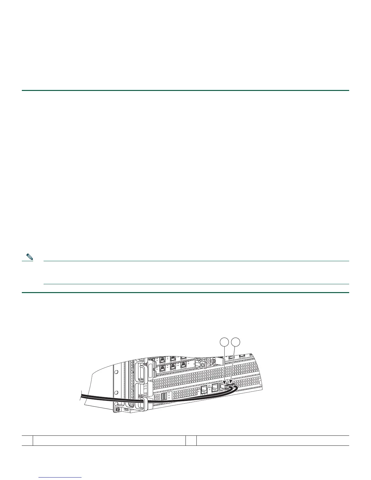
Figure 8 Cisco ASR1000 Route Processor Console and Auxiliary Port Connectors
1
CON—console port
2
AUX —auxiliary port
MI
N
A
C
O
MA
J
STB
Y
A
C
T
V
S
TA
T
ASR100
0-R
P
1
P
WR
C
R
I
T
0
S
PA
-4
X
O
C3
-
POS
0
1
2
3
A
A
/
L
C/A
A
/L
C/A
A/L
S
PA
-4
X
O
C
3
-P
O
S
S
TATUS
0
1
2
3
C/
A
A
/L
C/A
A
/
L
C/A
A
/
L
C/A
A
/L
SPA-4
X
O
C
3
-P
O
S
S
T
AT
US
0
1
2
3
C/
A
A
/L
C/A
A
/
L
C/A
A
/
L
C
/
A
A/L
B
I
T
S
C
O
N
A
UX
CA
R
R
IER
LIN
K
M
GMT
ET
H
E
R
N
E
T
DISK
HD
USB
DF
0
1
 Loading...


