EasyManuals Logo

Cisco ASR 9010 Installation Guide

Cisco ASR 9010
284 pages
To Next Page IconTo Next Page
To Previous Page IconTo Previous Page
Page #150 background imageLoading...
Page #150 background image
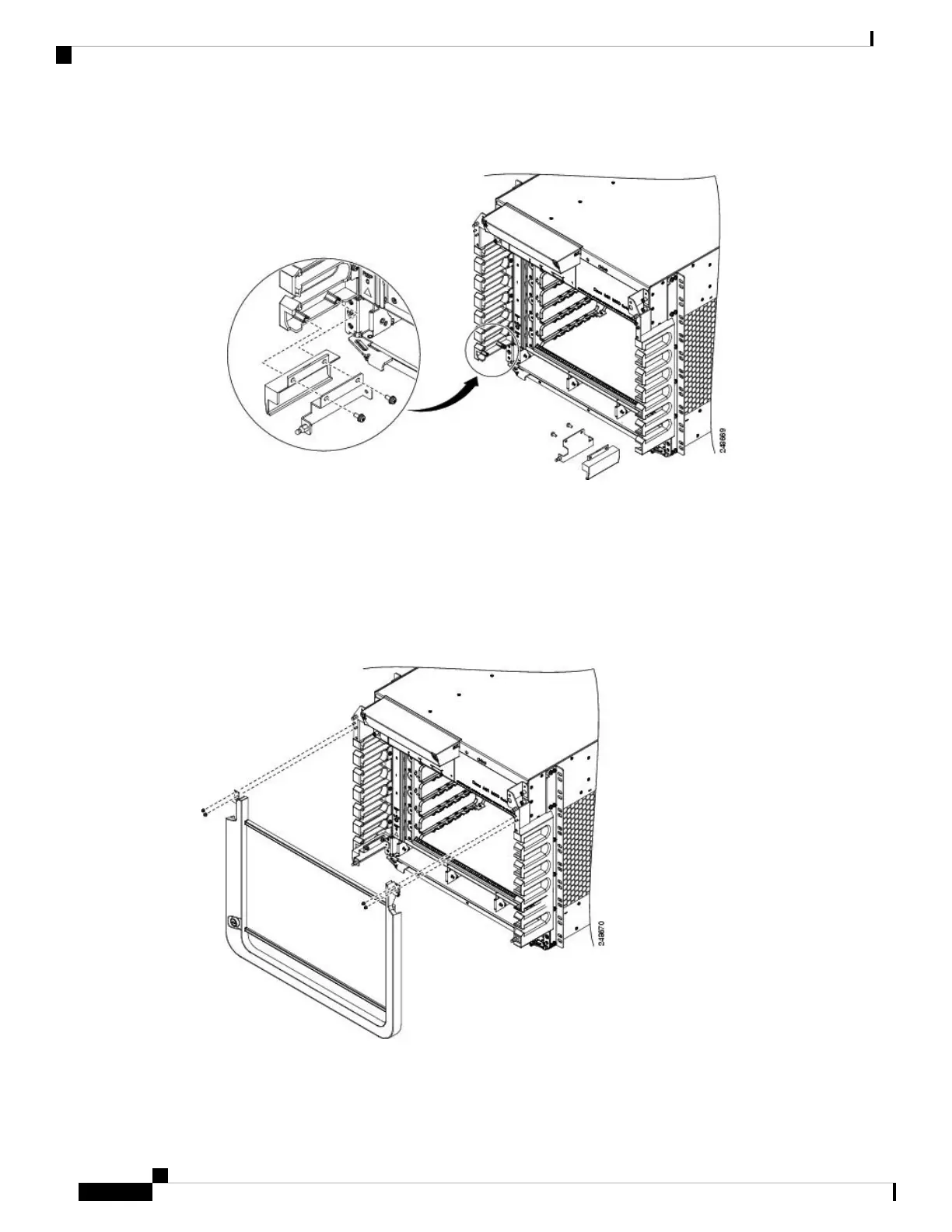
Figure 144: Installing Ball Stud Assemblies on the Cisco ASR 9006 Router (Shown with Version 1 Power System)
Step 3 Attach the door to the upper chassis panel (see the figure below) using two hex nuts per side to secure the
door hinges to the panel. Tighten the hex nuts to a torque of 4 in-lb (0.45 N-m).
Do not overtighten the hex nuts. They can be broken through overtightening.
Caution
When opening the door, be sure to grasp the center of the door to pull it open. Do not open the door
by pulling on a corner or side of the door frame.
Caution
Figure 145: Installing the Optional Accessory Door on the Cisco ASR 9006 Router
Cisco ASR 9000 Series Aggregation Services Router Hardware Installation Guide
136
Unpacking and Installing the Chassis
Installing Optional Chassis Accessories on the Cisco ASR 9006 Router

Table of Contents

Other manuals for Cisco ASR 9010

Questions and Answers:

Question and Answer IconNeed help?

Do you have a question about the Cisco ASR 9010 and is the answer not in the manual?

Cisco ASR 9010 Specifications

General IconGeneral
ChassisModular
Rack Units21 RU
Operating SystemCisco IOS XR
Form FactorRack-mountable
Number of Slots10
Power SupplyAC or DC
RedundancyYes
Slots8 line card slots, 2 route switch processor slots
Memory16 GB DRAM
Storage64 GB SSD (Route Processor)
Port TypesEthernet, OTN
Redundancy FeaturesRoute Processor, Power Supply, Fan Tray
Operating Temperature32 to 104°F (0 to 40°C)
Humidity5% to 90% non-condensing
Route ProcessorCisco ASR 9000 Series Route Switch Processor

Related product manuals