EasyManuals Logo

Cisco ASR 9010 Installation Guide

Cisco ASR 9010
284 pages
To Next Page IconTo Next Page
To Previous Page IconTo Previous Page
Page #223 background imageLoading...
Page #223 background image
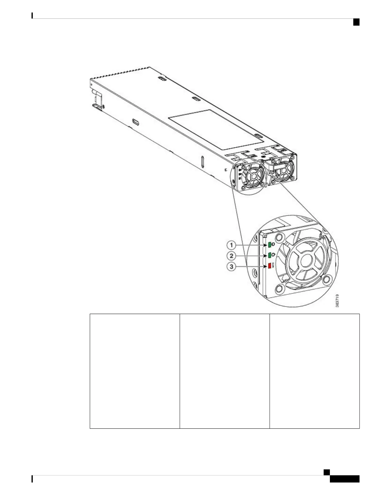
Figure 201: Version 3 DC Power Module Status Indicators
ON continuously when the input
voltage is present and within the
correct range
BLINKING when the input voltage
is out of acceptable range
On the DC power tray,
the Power Input LED is
lit solid green if both
DC feeds are valid and
blinks green if only a
single DC feed is valid.
Note
OFF when no input voltage is
present
Input power LED1
Cisco ASR 9000 Series Aggregation Services Router Hardware Installation Guide
209
Troubleshooting the Installation
Troubleshooting the DC Input Power Subsystem

Table of Contents

Other manuals for Cisco ASR 9010

Questions and Answers:

Question and Answer IconNeed help?

Do you have a question about the Cisco ASR 9010 and is the answer not in the manual?

Cisco ASR 9010 Specifications

General IconGeneral
ChassisModular
Rack Units21 RU
Operating SystemCisco IOS XR
Form FactorRack-mountable
Number of Slots10
Power SupplyAC or DC
RedundancyYes
Slots8 line card slots, 2 route switch processor slots
Memory16 GB DRAM
Storage64 GB SSD (Route Processor)
Port TypesEthernet, OTN
Redundancy FeaturesRoute Processor, Power Supply, Fan Tray
Operating Temperature32 to 104°F (0 to 40°C)
Humidity5% to 90% non-condensing
Route ProcessorCisco ASR 9000 Series Route Switch Processor

Related product manuals