5-6
Catalyst 3650 Switch Hardware Installation Guide
OL-29734-01
Chapter 5 Troubleshooting
Finding the Switch’s Serial Number
Step 2 Start the terminal emulation program on the PC or the terminal. The program, frequently a PC
application, such as HyperTerminal or ProcommPlus, makes communication between the switch and
your PC or terminal possible.
The switch LEDs begin blinking after about 2 seconds. If the LEDs above the mode button turn solid
green, you can release the Mode button and run Express Setup to configure the switch. If the LEDs do
not turn solid green, continue with the next step.
Step 3 Continue holding down the Mode button. The LEDs stop blinking after an additional 8 seconds, and then
the switch reboots
You can also configure the switch by using the CLI setup procedure.
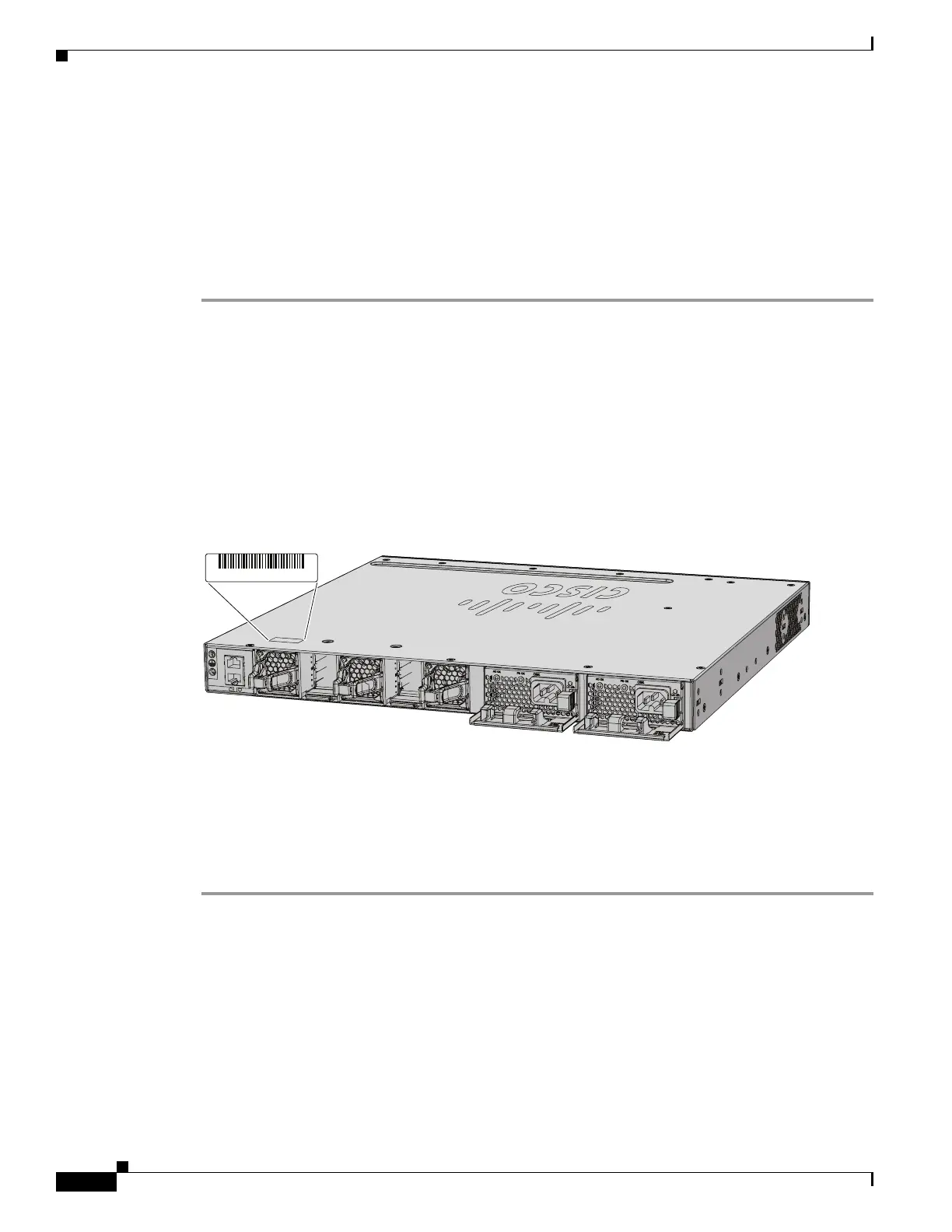
Finding the Switch’s Serial Number
If you contact Cisco Technical Assistance, you should know the switch’s serial number. Figure 5-1
shows the serial number location. You can also use the show version privileged EXEC command to see
the switch’s serial number.
Figure 5-1 Switch Serial Number Location
Replacing a Failed Data Stack Member
To replace a failed data stack member:
Step 1 Power down the failed switch. Remove the AC or DC input power.
Step 2 Make sure the replacement switch is powered off, and then connect it to the stack.
If you had manually set the member numbers for the switch stack, manually assign the member number
of the failed switch to the replacement switch. To manually assign the stack member number, see the
Cisco Catalyst 3650 Series Switches Software Configuration Guides at
http://www.cisco.com/c/en/us/support/switches/catalyst-3650-series-switches/products-installation-an
d-configuration-guides-list.html.
Step 3 Make the same Gigabit Ethernet connections on the replacement switch as those that were on the failed
switch.
Step 4 Reinstall modules and cable connections, if any.
PWR
-C
2
-6
4
0
W
A
C
PWR
-C
2
-6
4
0
W
A
C
SN: XXXNNNNXXXX
347807, 781-00797-01
CONSOLE
MGMT

 Loading...


