EasyManuals Logo

Cisco Catalyst 3650 Series Hardware Installation Guide

Cisco Catalyst 3650 Series
126 pages
To Next Page IconTo Next Page
To Previous Page IconTo Previous Page
Page #30 background imageLoading...
Page #30 background image
1-20
Catalyst 3650 Switch Hardware Installation Guide
OL-29734-01
Chapter 1 Product Overview
Front Panel
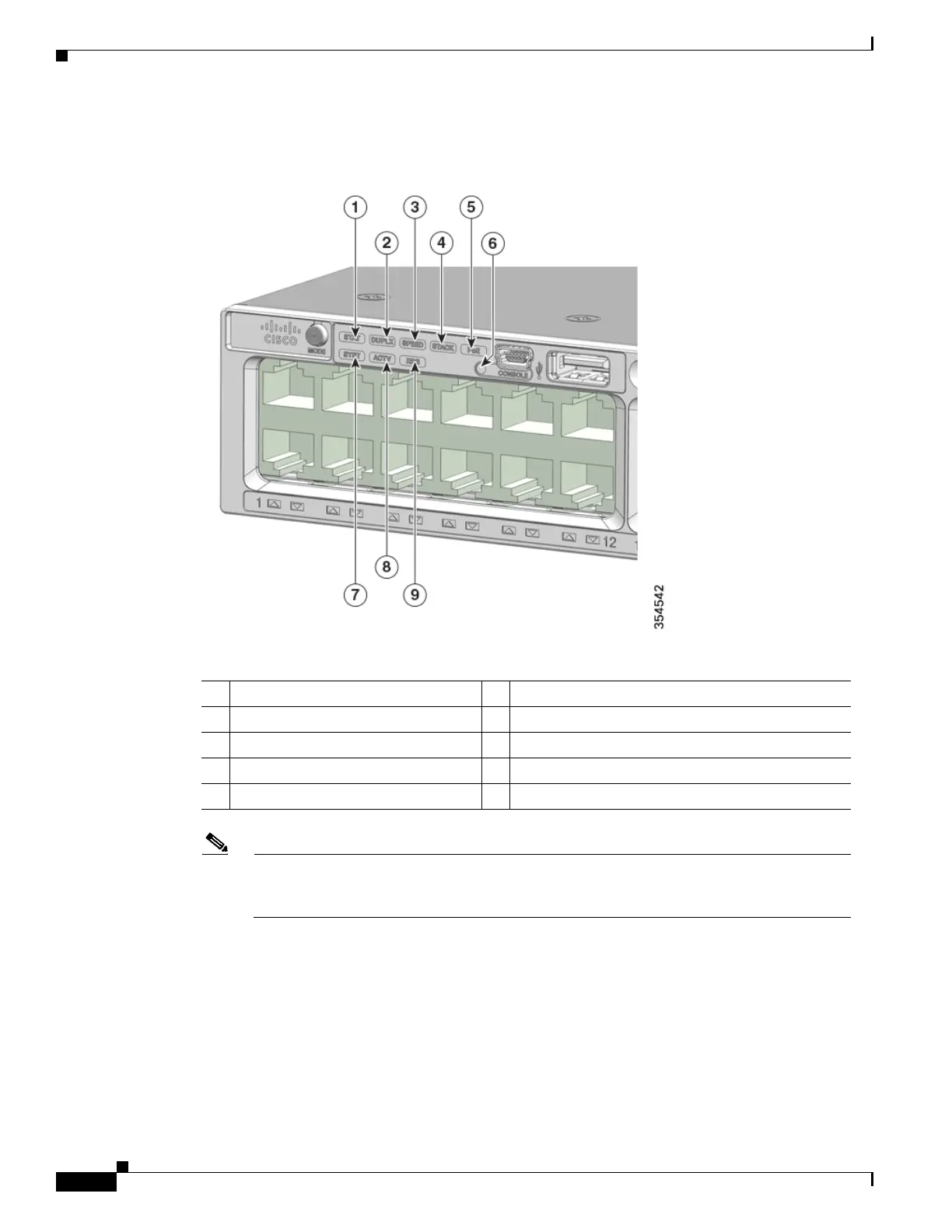
Figure 1-9 Catalyst 3650-24PDM and Catalyst 3650-48FQM Switches Front Panel LEDs
SYST LED
The LED colors for the switch and their corresponding status indications are given below:
1 STAT (status) 6
CONSOLE (USB mini-Type B (console) port
2 DUPLX (duplex) 7 SYST (system)
3 SPEED 8 ACTV (active)
4 STACK 9 RPS
5 PoE
1
1. Only switches with PoE+ ports.
Note The illustrations of the Catalyst 3650 switch are not intended to depict any particular color
scheme. They are provided as a reference for various features and markings described within
this guide.

Table of Contents

Other manuals for Cisco Catalyst 3650 Series

Questions and Answers:

Question and Answer IconNeed help?

Do you have a question about the Cisco Catalyst 3650 Series and is the answer not in the manual?

Cisco Catalyst 3650 Series Specifications

General IconGeneral
RAM4 GB
Flash Memory4 GB
Ports24 or 48 10/100/1000 Ethernet ports
Uplinks4 x 1G SFP or 4 x 10G SFP+ (depending on model)
StackingUp to 9 switches with StackWise-160
Layer SupportLayer 2, Layer 3
SoftwareCisco IOS Software
Power SupplyInternal power supply; optional redundant power supply available
Storage Temperature-40°F to 158°F (-40°C to 70°C)

Related product manuals