2-5
Catalyst 3650 Switch Hardware Installation Guide
OL-29734-01
Appendix 2 Connector and Cable Specifications
Cable and Adapter Specifications
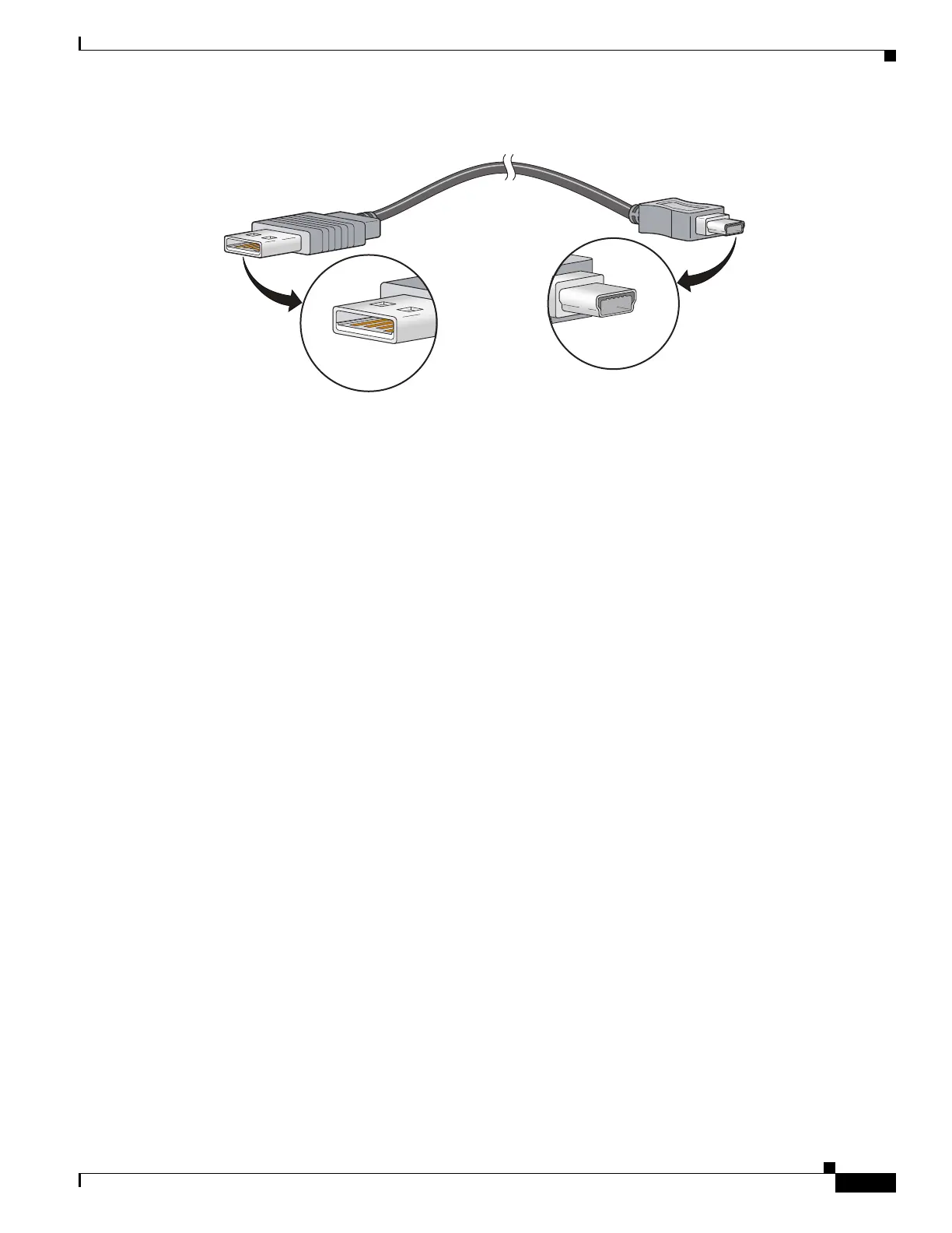
Figure 2-10 USB Type A-to-USB 5-Pin Mini-Type B Cable
The RJ-45 console port uses an 8-pin RJ-45 connector (See Table 2-2 and Table 2-3.) The supplied
RJ-45-to-DB-9 adapter cable is used to connect the console port of the switch to a console PC. Provide
an RJ-45-to-DB-25 female DTE adapter if you want to connect the switch console port to a terminal.
You can order a kit (part number ACS-DSBUASYN=) containing that adapter. For console port and
adapter pinout information, see Table 2-2 and Table 2-3.
Cable and Adapter Specifications
• StackWise Cables, page 2-5
• StackWise Adapters, page 2-6
• StackWise Adapter Blanks, page 2-7
• SFP and SFP+ Module Cable Specifications, page 2-8
• Four Twisted-Pair Cable Pinouts, page 2-8
• Two Twisted-Pair Cable Pinouts, page 2-9
• Identifying a Crossover Cable, page 2-9
• Console Port Adapter Pinouts, page 2-9
StackWise Cables
Figure 2-11 shows a StackWise stacking cable.

 Loading...


