1-37
Catalyst 3650 Switch Hardware Installation Guide
OL-29734-01
Chapter 1 Product Overview
Rear Panel
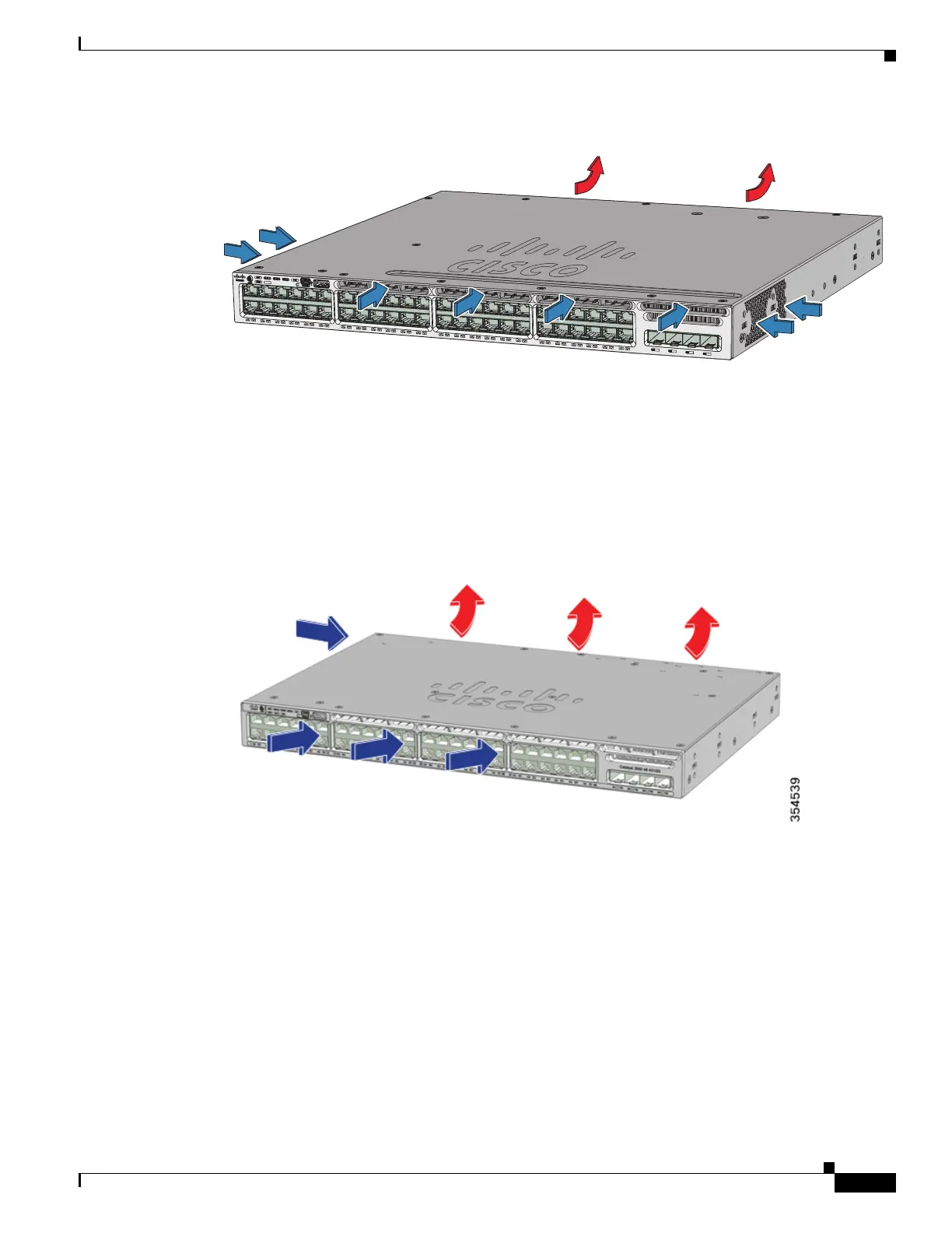
Figure 1-16 24-Port and 48-Port Switch Airflow Patterns
Fan Airflow for Catalyst 3650-24PDM and Catalyst 3650-48FQM Switches
The Catalyst 3650-24PDM and Catalyst 3650-48FQM switches have fixed fan modules. Unlike the other
Catalyst 3650 switches, they do not have slots for changing the fan modules.
Figure 1-17 Catalyst 3650-24PDM and Catalyst 3650-48FQM Switches’ Airflow Pattern
Management Ports
The switch configurations can be managed through a 10/100/1000 Ethernet port or an RJ-45 console
port.
Ethernet Management Port
You can connect the switch to a host such as a Windows workstation or a terminal server through the
10/100/1000 Ethernet management port, or one of the console ports (see Figure 1-13). The 10/100/1000
Ethernet management port is a VPN routing and forwarding interface and uses an RJ-45 crossover cable
or straight-through cable.
C
a
t
al
yst
3650
48P
oE
+
4X
1
G
347812
01X
13X
12
X
24X
25
X
3
6X
3
7X
48X

 Loading...


