EasyManuals Logo

Cisco Catalyst 3650 Series Hardware Installation Guide

Cisco Catalyst 3650 Series
126 pages
To Next Page IconTo Next Page
To Previous Page IconTo Previous Page
Page #111 background imageLoading...
Page #111 background image
2-3
Catalyst 3650 Switch Hardware Installation Guide
OL-29734-01
Appendix 2 Connector and Cable Specifications
Connector Specifications
SFP and SFP+ Modules
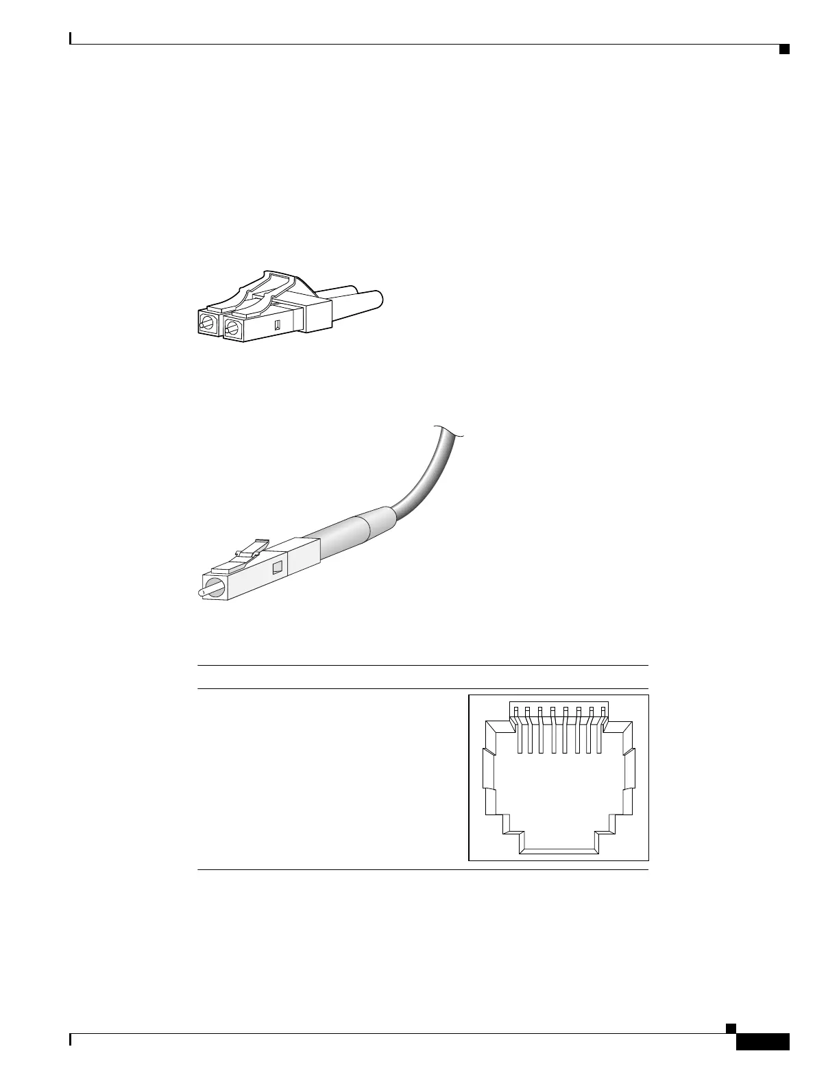
Figure 2-4, Figure 2-5, and Figure 2-6 show the SFP module connectors.
The switch supports the SFP module patch cable, a 0.5-meter, copper, passive cable with SFP module
connectors at each end (Figure 2-7). This cable can be used (only with 1-Gigabit Ethernet SFP ports) to
connect two Catalyst 3650 switches in a cascaded configuration.
Figure 2-4 Duplex LC Cable Connector
Figure 2-5 Simplex LC Cable Connector
Figure 2-6 Copper SFP Module RJ-45 Connector
58476
57
834
60915
2 3145678Pin Label
1
2
3
4
5
6
7
8
TP0+
TP0-
TP1+
TP2+
TP2-
TP1-
TP3+
TP3-

Table of Contents

Other manuals for Cisco Catalyst 3650 Series

Questions and Answers:

Question and Answer IconNeed help?

Do you have a question about the Cisco Catalyst 3650 Series and is the answer not in the manual?

Cisco Catalyst 3650 Series Specifications

General IconGeneral
RAM4 GB
Flash Memory4 GB
Ports24 or 48 10/100/1000 Ethernet ports
Uplinks4 x 1G SFP or 4 x 10G SFP+ (depending on model)
StackingUp to 9 switches with StackWise-160
Layer SupportLayer 2, Layer 3
SoftwareCisco IOS Software
Power SupplyInternal power supply; optional redundant power supply available
Storage Temperature-40°F to 158°F (-40°C to 70°C)

Related product manuals