4-6
Catalyst 3650 Switch Hardware Installation Guide
OL-29734-01
Chapter 4 Power Supply Installation
Installation Guidelines
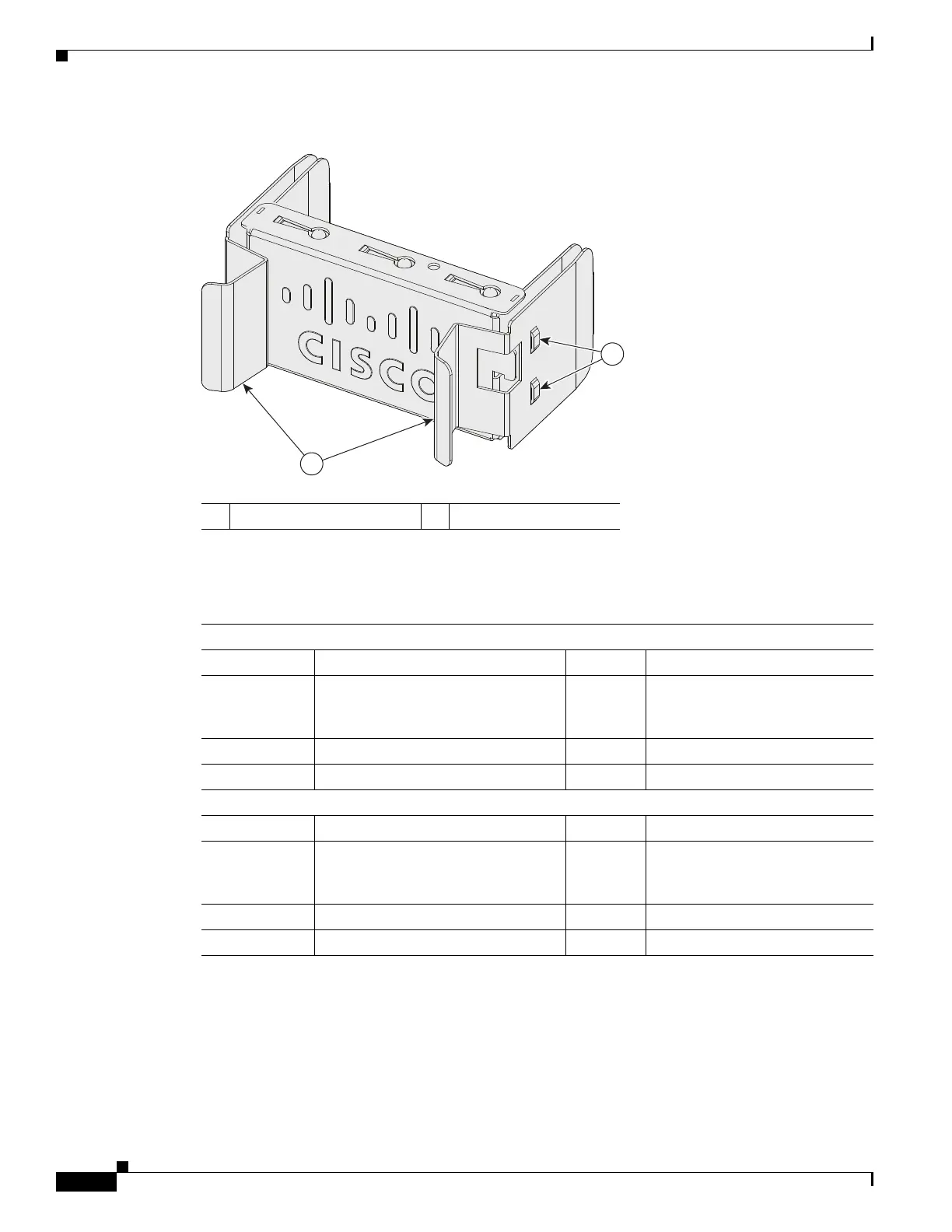
Figure 4-7 Power Supply Slot Blank Cover
The power supply modules have two status LEDs:
Installation Guidelines
Table 4-1 lists the switches and the compatible power supply modules. Observe these guidelines when
removing or installing a power supply or fan module:
1 Release handles 2 Retainer clips
Table 4-2 Switch Power Supply Module LEDs
AC Power Supply Module LEDs
AC OK Description PS OK Description
Off
(AC LED is
off)
No AC input power. Off Output is disabled, or input is
outside operating range.
Green AC input power present. Green Power output to switch.
Red Output has failed.
DC Power Supply Module LEDs
DC OK Description PS OK Description
Off
(DC LED is
off)
No DC input power. Off Output is disabled, or input is
outside operating range.
Green DC input power present. Green Power output to switch.
Red Output has failed.

 Loading...


