4-5
Catalyst 3650 Switch Hardware Installation Guide
OL-29734-01
Chapter 4 Power Supply Installation
Power Supply Module Overview
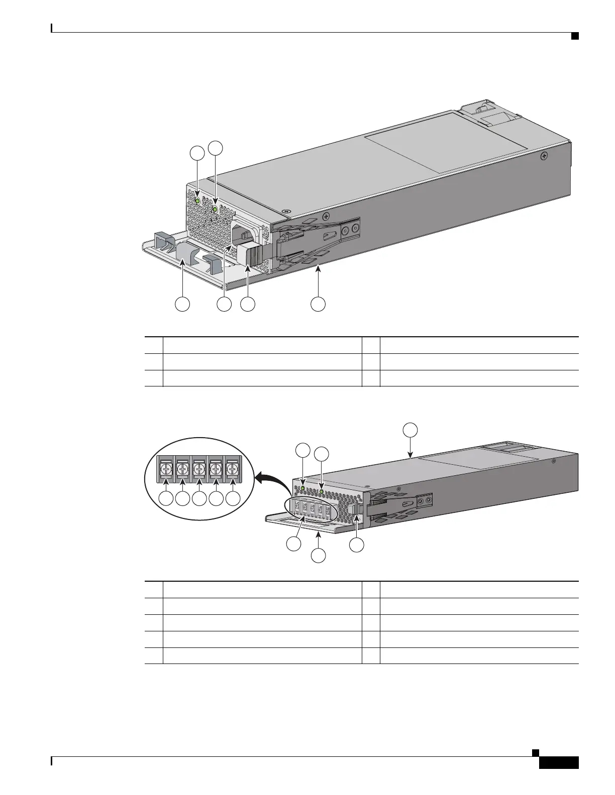
Figure 4-5 250-W AC Power Supply Module
Figure 4-6 640-W DC Power Supply Module
If no power supply is installed in a power supply slot, install a power supply slot blank cover
(Figure 4-7).
1 AC OK LED 4 AC power cord connector
2 PS OK LED 5 Release latch
3 AC power cord retainer 6 250-W AC power supply module
P
S
OK
AC OK
P
W
R-C2-250W
AC
347622
3 5 6
4
1
2
1 640-W DC power supply module 6 Grounding terminal
2 DC OK LED 7 Release latch
3 PS OK LED 8 Extraction handle
4 Input power terminals (positive polarity) 9 Terminal block safety cover
5 Input power terminals (negative polarity)
DC OK
P
W
R-C2-640WDC
PS OK
D
C
I
N
P
U
T
-
36V
t
o-
-72V
=
=
21-
10.
5A
OU
T
P
U
T
640
W
MA
X
+
12V
==
/
20.
83
A
-
54V
==
/
7.
36 A
347784
1
8
2
3
7
4
5 6 5 4
9

 Loading...


