EasyManuals Logo

Cisco Catalyst 4500e Series User Manual

Cisco Catalyst 4500e Series
152 pages
To Next Page IconTo Next Page
To Previous Page IconTo Previous Page
Page #79 background imageLoading...
Page #79 background image
4-5
Catalyst 4500 E-Series Switches Installation Guide
OL-13972-01
Chapter 4 Removing and Replacing FRUs
Removing and Replacing the Power Supply
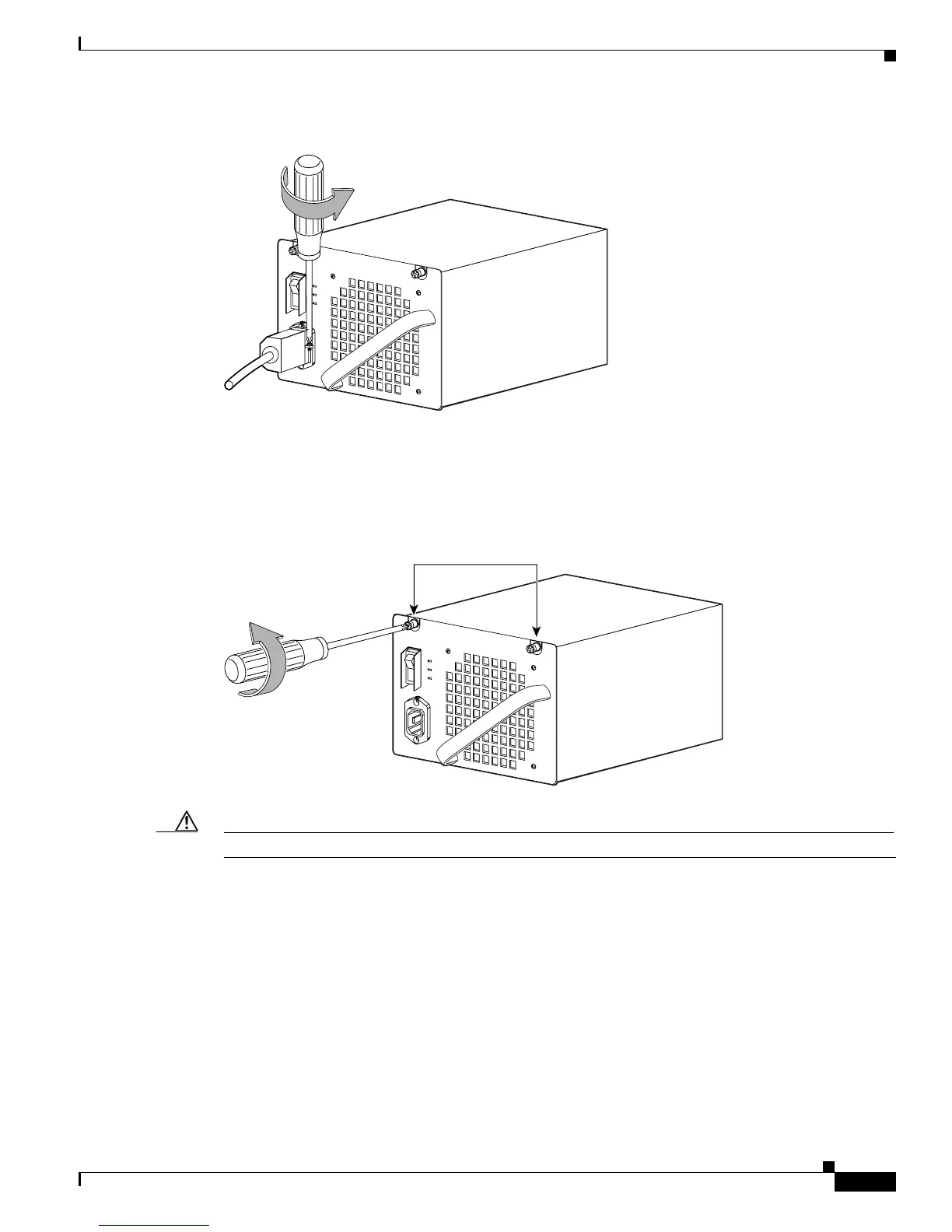
Figure 4-6 Loosening the Side-Clamp Screw
Step 3 Disconnect the power cord from the power supply being removed.
Step 4 Loosen the two captive screws (see Figure 4-7).
Figure 4-7 Loosening the Captive Screws
Caution Use both hands to grasp a power supply.
Step 5 Grasp the power supply handle with one hand. Place your other hand underneath to support the bottom
of the power supply, as shown in
Figure 4-8.
79139
Captive screws
79140

Table of Contents

Questions and Answers:

Question and Answer IconNeed help?

Do you have a question about the Cisco Catalyst 4500e Series and is the answer not in the manual?

Cisco Catalyst 4500e Series Specifications

General IconGeneral
SeriesCatalyst 4500E Series
StackableNo
Chassis Options3-slot, 6-slot, 7-slot, 10-slot
Power Supply OptionsAC, DC
RedundancyPower supply redundancy, supervisor engine redundancy (1+1)
Layer SupportLayer 2
VirtualizationYes (Virtual Switching System - VSS)
Form FactorModular
PortsGigabit Ethernet, 10 Gigabit Ethernet, 40 Gigabit Ethernet, and 100 Gigabit Ethernet options depending on the line cards
Jumbo Frame SupportYes
FeaturesFlexible NetFlow, TrustSec
Maximum Port DensityUp to 384 ports per chassis
Operating SystemCisco IOS XE
ManagementCLI, SNMP, Cisco Prime Infrastructure, Cisco DNA Center
Security Features802.1X
VLAN SupportUp to 4096 VLANs
QoS SupportYes
Supervisor Engine OptionsSup8-E

Related product manuals