1-22
Catalyst 4500 E-Series Switches Installation Guide
OL-13972-01
Chapter 1 Product Overview
Supervisor Engines
• RESET Button, page 1-24
• Compact Flash Slot, page 1-24
LEDs
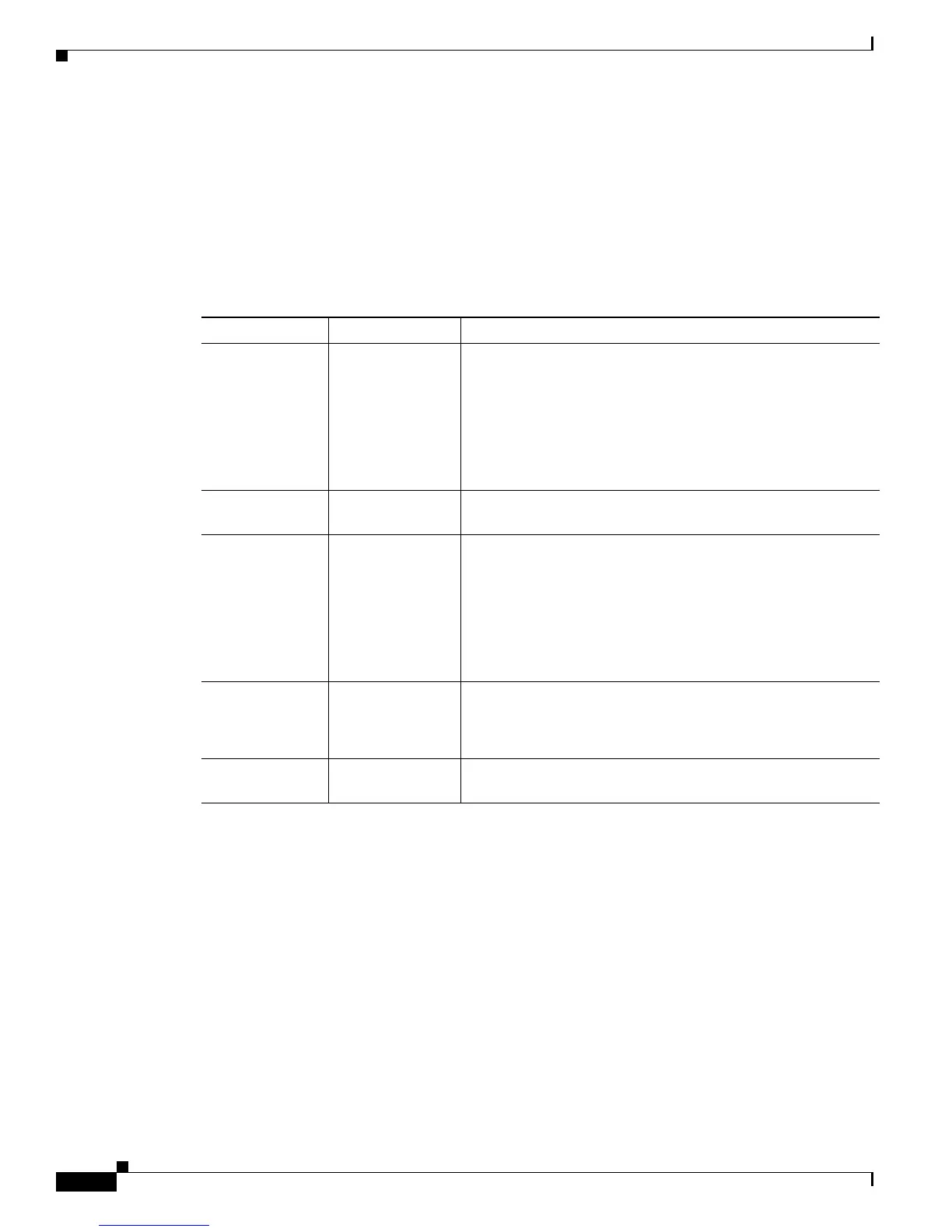
Table 1-6 describes the supervisor engine LEDs.
Gigabit Ethernet Uplink Ports
The Gigabit Ethernet uplink ports operate in full-duplex mode only. GBICs have SC connectors to
interface with multimode fiber (MMF) and single-mode fiber (SMF) cable. For more information about
GBICs, refer to the Catalyst
4500 Series Module Installation Guide. Frequently updated compatibility
information for GBICs, X2s, and SFPs are in documents at:
http://www.cisco.com/en/US/products/hw/modules/ps5455/products_device_support_tables_list.html
When two Supervisor Engine Vs are present in a Catalyst 4507R-E and Catalyst 4510R-E, all four
uplinks are active on both Primary (active) and Secondary (standby) supervisor engines by default, or
two uplinks are active in a non-redundant configuration. This limits access to slot 10 on the Catalyst
4510R to ports 3 and 4 only. You can only use the 2-port Gigabit Ethernet switching module
(WS-X4302-GB) in slot 10 (flex-slot) when a Supervisor Engine V is used.
Ta b l e 1-6 Supervisor Engine LEDs
LED Color/State Description
STATUS Indicates the results of a series of self-tests:
Green All diagnostic tests passed.
Red A test failed.
Orange System boot or diagnostic test is in progress, or two power
supplies are installed but only one is turned on.
Off Module is disabled.
UTILIZATION Green 1–100% If the switch is operational, this display indicates the current
traffic load over the backplane (as an approximate percentage).
LINK Indicates the status of the 10/100BASE-T port,
10/100/1000BASE-T or uplink ports:
Green The link is operational.
Orange The link is disabled by user.
Flashing orange The power-on self-test indicates a faulty port.
Off No signal is detected or there is a link configuration failure.
ACTIVE Indicates whether the uplink port is active or not:
(uplink port) Green The port is active.
Off The port is not active.
ACTIVE The LED to the right of the uplink ports is only used in switches
with two supervisors. The LED lights on the active supervisor.