4-7
Catalyst 4500 E-Series Switches Installation Guide
OL-13972-01
Chapter 4 Removing and Replacing FRUs
Removing and Replacing the Power Supply
Step 6 Using a screwdriver, tighten the two captive installation screws (see Figure 4-1) on the front panel of the
AC-input power supply.
Step 7 Make sure the power supply power switch is in the off position (O).
Step 8 Before you connect the power supply to a power source, ensure that all site power and grounding
requirements have been met.
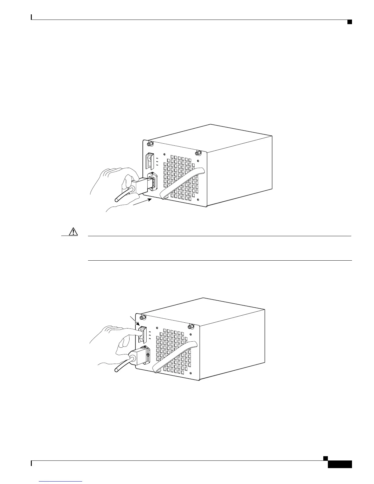
Step 9 Plug the power cord into the power supply (see Figure 4-9).
Figure 4-9 Plugging the Power Cord into the Power Supply
Step 10 Connect the other end of the power cord to an AC-power input source.
Caution In a system with multiple power supplies, connect each power supply to a separate AC power source. In
the event of a power source failure, if the second source is still available, it can maintain maximum
overcurrent protection for each power connection.
Step 11 Press the power switch down to the on (|) position (see Figure 4-10).
Figure 4-10 Powering On the Power Supply
Step 12 Verify power supply operation by checking the power supply’s front-panel LEDs. You should see the
following:
• The LED labeled GOOD is green.
• The LED labeled FAIL is not lit.
• The LED labeled FAN OK is green.
79142
Power switch
79143