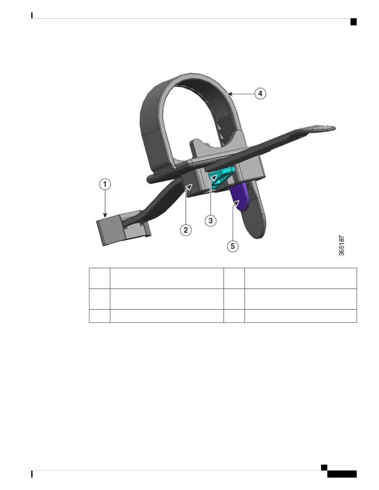
Figure 30: Parts of the Power Cord Retainer
Flexible retainer strip4The end that is fixed to the power supply
module
1
Retainer strip latch5Clamp which can move towards the power
supply or away from it
2
--Clamp latch3
Installation and Removal Sequence
Installation—After you have inserted the power supply module into the bay, first position the clamp closest
to the power supply, near the plug round cylinder stress relief and then insert the flexible retainer strip into
the clamp hole and tighten. The clamp cannot be moved after the flexible retainer strip is inserted into the
clamp hole.
Removal—After you have turned off the power supply module's rocker switch, first remove the flexible
retainer strip from the clamp hole and then adjust the position of the clamp to remove the power cord.
Positioning the Clamp
In Figure 31: Positioning the Clamp, the clamp can always move freely in direction 3a.
Cisco Catalyst 9400 Series Switches Hardware Installation Guide
99
Removing and Replacing FRUs
Power Cord Retainer Mechanism