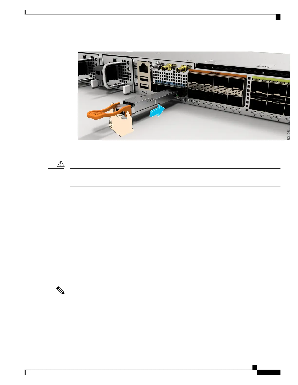
Figure 32: Installing a Bale Clasp QSFP+, QSFP28, or QSFP-DD Transceiver Module
8. Press firmly on the front of the QSFP+, QSFP28, or QSFP-DD transceiver module with your thumb to
fully seat the transceiver in the module’s transceiver socket.
If the latch is not fully engaged, you might accidentally disconnect the QSFP+, QSFP28, or QSFP-DD
transceiver module.
Caution
9. For optical QSFP+, QSFP28, or QSFP-DD transceiver modules, reinstall the dust plug into the transceivers
optical bore until you are ready to attach the network interface cable. Do not remove the dust plug until
you are ready to attach the network interface cable.
Attach the Optical Network Cable
Before you begin
Before you remove the dust plugs and make any optical connections, follow these guidelines:
• Keep the protective dust plugs installed in the unplugged fiber-optic cable connectors and in the transceiver
optical bores until you are ready to make a connection.
• Inspect and clean the MPO connector end faces just before you make any connections.
• Grasp the MPO connector only by the housing to plug or unplug a fiber-optic cable.
40-Gigabit QSFP+, QSFP28, or QSFP-DD transceiver modules are keyed to prevent incorrect insertion.
Note
Cisco Network Convergence System 540 Large Density Routers Hardware Installation Guide
53
Install the Device
Attach the Optical Network Cable