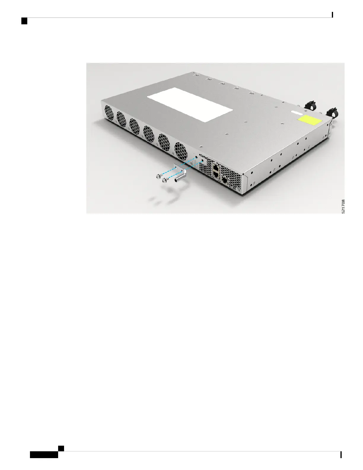
Figure 18: Ground Lug
2. Attach one end of the shelf ground cable (#6 AWG cable) to the ground point on the rear of the chassis
using the specified dual-hole lug connector.
• Use a wire-stripping tool to remove approximately 0.75 inches (19 mm) of the covering from the
end of the grounding cable.
• Insert the stripped end of the grounding cable into the open end of the grounding lug.
• Use the crimping tool to secure the grounding cable in the grounding lug.
• Remove the adhesive label from the grounding pad on the chassis.
• Place the grounding lug against the grounding pad so that there is solid metal-to-metal contact, and
insert the two M4 screws with washers through the holes in the grounding lug and into the grounding
pad.
• Ensure that the lug and cable do not interfere with other equipment.
• Prepare the other end of the grounding cable and connect it to an appropriate grounding point in your
site to ensure adequate earth ground.
Install the AC Power Cables
Refer Chapter 6: Replace Power Supply for more information about AC power cables installation.
To install the AC power cables in the power supply slots:
1. Plug the power supply cord in the power supply module.
Cisco Network Convergence System 540 Large Density Routers Hardware Installation Guide
36
Install the Device
Install the AC Power Cables