1-129
Cisco ONS 15454 SDH Troubleshooting Guide, R5.0
July 2005
Chapter 1 General Troubleshooting
1.10.15 Ethernet Connections
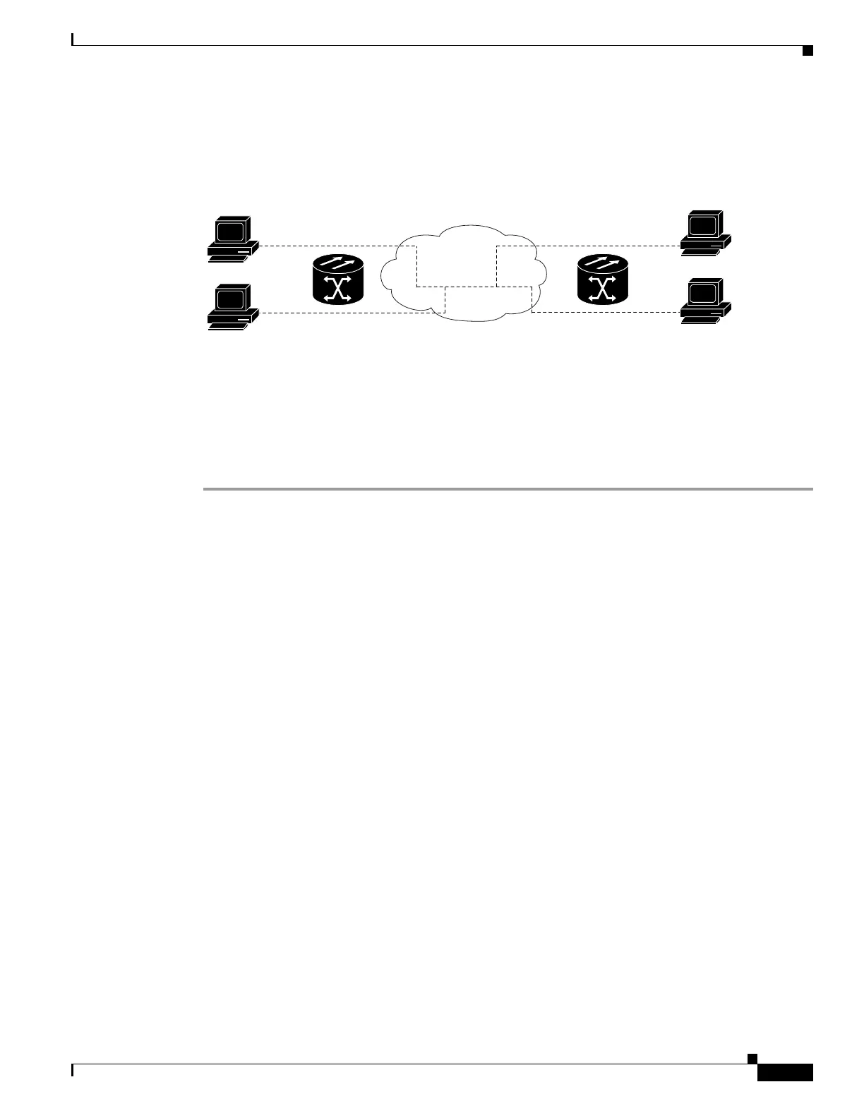
Figure 1-49 Ethernet Connectivity Reference
Verify Ethernet Connections
Step 1 Verify that the alarm filter is turned OFF.
Step 2 Check for SDH/MXP/TXP/FC_MR alarms on the VC that carries the VLAN No. 1 Ethernet circuit.
Clear any alarms by looking them up in Chapter 2, “Alarm Troubleshooting.”
Step 3 Check for Ethernet-specific alarms. Clear any raised alarms by looking up that alarm in Chapter 2,
“Alarm Troubleshooting.”
Step 4 Verify that the ACT LED on the Ethernet card is green.
Step 5 Verify that Ports 1 and 3 on ONS 15454 SDH No. 1 and Ports 1 and 2 on ONS 15454 SDH No. 2 have
green link-integrity LEDs illuminated.
Step 6 If no green link-integrity LED is illuminated for any of these ports, complete the following substeps:
a. Verify physical connectivity between the ONS 15454 SDH and the attached device.
b. Verify that the ports are enabled on the Ethernet cards.
c. Verify that you are using the proper Ethernet cable and that it is wired correctly, or replace the cable
with a known-good Ethernet cable.
d. Check the status LED on the Ethernet card faceplate to ensure the card booted up properly. This LED
should be steady green. If necessary, remove and reinsert the card and allow it to reboot.
e. It is possible that the Ethernet port is functioning properly but the link LED itself is broken.
Complete the procedures in the “Verify G-Series Ethernet or FC_MR-4 Card LED Operation”
section on page 1-105 or the “Verify E-Series and ML-Series Ethernet Card LED Operation” section
on page 1-106 as appropriate.
Step 7 Verify connectivity between device A and device C by pinging between these locally attached devices
(see the “1.9.8 Verify PC Connection to the ONS 15454 SDH (ping)” procedure on page 1-118). If the
ping is unsuccessful:
a. Verify that device A and device C are on the same IP subnet.
b. Open the Ethernet card in CTC card view and click the Provisioning > VLAN tabs to verify that
both Port 1 and Port 3 on the card are assigned to the same VLAN.
Virtual
LAN # 1
Device "A"
192.168.1.25
255.255.255.0
VLAN #1 Member
Device "C"
192.168.1.50
255.255.255.0
VLAN #1 Member
Device "D"
192.168.1.100
255.255.255.0
VLAN #1 Member
ONS Node #1
Port #1 VLAN #1
Port #3 VLAN #1
ONS Node #2
Port #1 VLAN #1
Port #2 VLAN #1
Device "B"
192.168.1.75
255.255.255.0
VLAN #1 Member
32167