1-36
Cisco ONS 15454 SDH Troubleshooting Guide, R5.0
July 2005
Chapter 1 General Troubleshooting
1.2.8 Perform a Terminal (Inward) Loopback on a Source-Node Electrical Port (East to West)
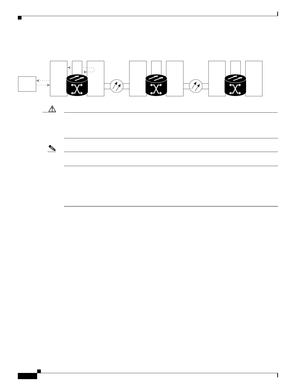
Figure 1-18 Terminal (Inward) Loopback on a Source Electrical Port
Caution Performing a loopback on an Unlocked circuit is service-affecting. To protect traffic, apply a lockout or
Force switch to the target loopback port. See the “2.10.2 Protection Switching, Lock Initiation, and
Clearing” section on page 2-260 for basic instructions. For more information about these operations,
refer to the Cisco ONS 15454 SDH Procedure Guide Chapter 15, “Maintain the Node.”
Note Electrical circuit terminal loopbacks do not transmit an AIS condition in the direction away from the
loopback. Instead of an AIS, a continuance of the signal transmitted to the loopback is provided.
Complete the “Create the Terminal (Inward) Loopback on a Source-Node Electrical Port” procedure on
page 1-36.
Create the Terminal (Inward) Loopback on a Source-Node Electrical Port
Step 1 Connect an electrical test set to the port you are testing:
a. If you just completed the “1.2.7 Perform an XC Loopback on a Source-Node STM-N VC (East to
West) Carrying an Electrical Circuit” procedure on page 1-32, leave the electrical test set hooked up
to the electrical port in the source node.
b. If you are starting the current procedure without the electrical test set hooked up to the electrical
port, use appropriate cabling to attach the Tx and Rx terminals of the electrical test set to the
electrical panel or the FMEC connectors for the port you are testing. Both Tx and Rx connect to the
same port.
Step 2 Adjust the test set accordingly.
Step 3 In CTC node view, click the Circuits tab and click Create.
Step 4 In the Circuit Creation dialog box, choose the type and size, such as VC HO Path Circuit, and the
number, such as 1.
Step 5 Click Next.
Step 6 In the next Circuit Creation dialog box, give the circuit an easily identifiable name such as ENtoEN.
Step 7 Leave the Bidirectional check box checked.
Step 8 Click Next.
Step 9 In the Circuit Creation source dialog box, select the Node, Slot, Port, and VC4 where the test set is
connected.
Step 10 Click Next.
Destination
ONS Node
STM-N STM-NXC
Source
ONS Node
Intermediate
ONS Node
STM-N STM-NXCSTM-N
Test Set
STM-N XC
90600