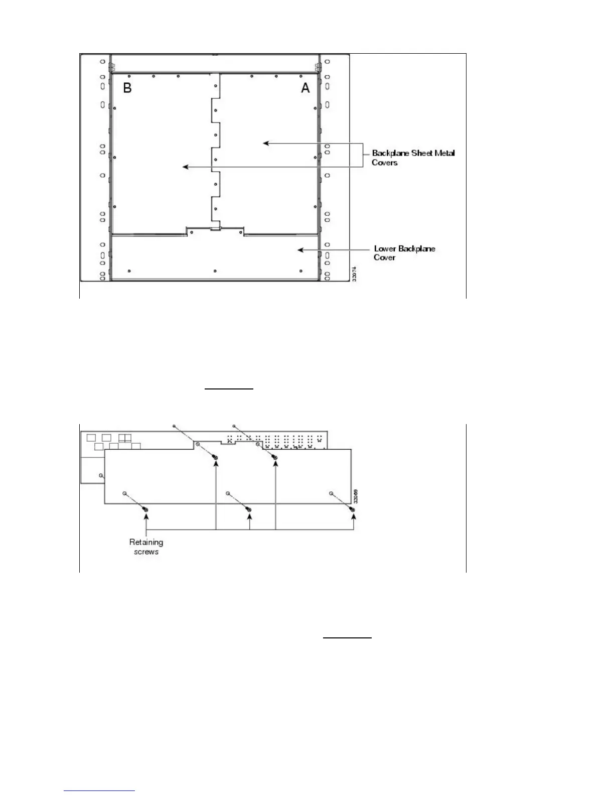
Lower Backplane Cover
The lower section of the ONS 15454 backplane is covered by either a clear plastic protector
(15454-SA-ANSI) or a sheet metal cover (15454-SA-HD), which is held in place by five 6-32 x 1/2 inch
screws. Remove the lower backplane cover to access the alarm interface panel (AIP), alarm pin fields, frame
ground, and power terminals (Figure 1-10).
Figure 1-10: Removing the Lower Backplane Cover
Rear Cover
The ONS 15454 has an optional clear plastic rear cover. This clear plastic cover provides additional
protection for the cables and connectors on the backplane. Figure 1-11 shows the rear cover screw locations.
Figure 1-11: Backplane Attachment for Cover
ONS_15454_Reference_Manual_R8.5.x_--_Shelf_and_Backplane_Hardware
Figure 1-9: Backplane Covers 12
 Loading...


