forth). As you face the rear of the ONS 15454 shelf assembly, the right side is the A side and the left side is
the B side. The top of the EIA connector columns are labeled with the corresponding slot number, and EIA
connector pairs are marked transmit (Tx) and receive (Rx) to correspond to transmit and receive cables.
Note: For information about EIA types, protection schemes, and card slots, see Card Protection.
EIA Installation
Optional EIA backplane covers are typically preinstalled when ordered with the ONS 15454. A minimal
amount of assembly might be required when EIAs are ordered separately from the ONS 15454. If you are
installing EIAs after the shelf assembly is installed, plug the EIA into the backplane. The EIA has six
electrical connectors that plug into six corresponding backplane connectors. The EIA backplane must replace
the standard sheet metal cover to provide access to the coaxial cable connectors. The EIA sheet metal covers
use the same screw holes as the solid backplane panels, but they have 12 additional 6-32 x 1/2 inch Phillips
screw holes so you can screw down the cover and the board using standoffs on the EIA board.
When using the RG-179 coaxial cable on an EIA, the maximum distance available (122 feet [37 meters]) is
less than the maximum distance available with standard RG-59 (734A) cable (306 feet [93 meters]). The
maximum distance when using the RG-59 (734A) cable is 450 feet (137 meters). The shorter maximum
distance available with the RG179 is due to a higher attenuation rate for the thinner cable. Attenuation rates
are calculated using a DS-3 signal:
For RG-179, the attenuation rate is 59 dB/kft at 22 MHz.•
For RG-59 (734A) the attenuation rate is 11.6 dB/kft at 22 MHz.•
EIA Configurations
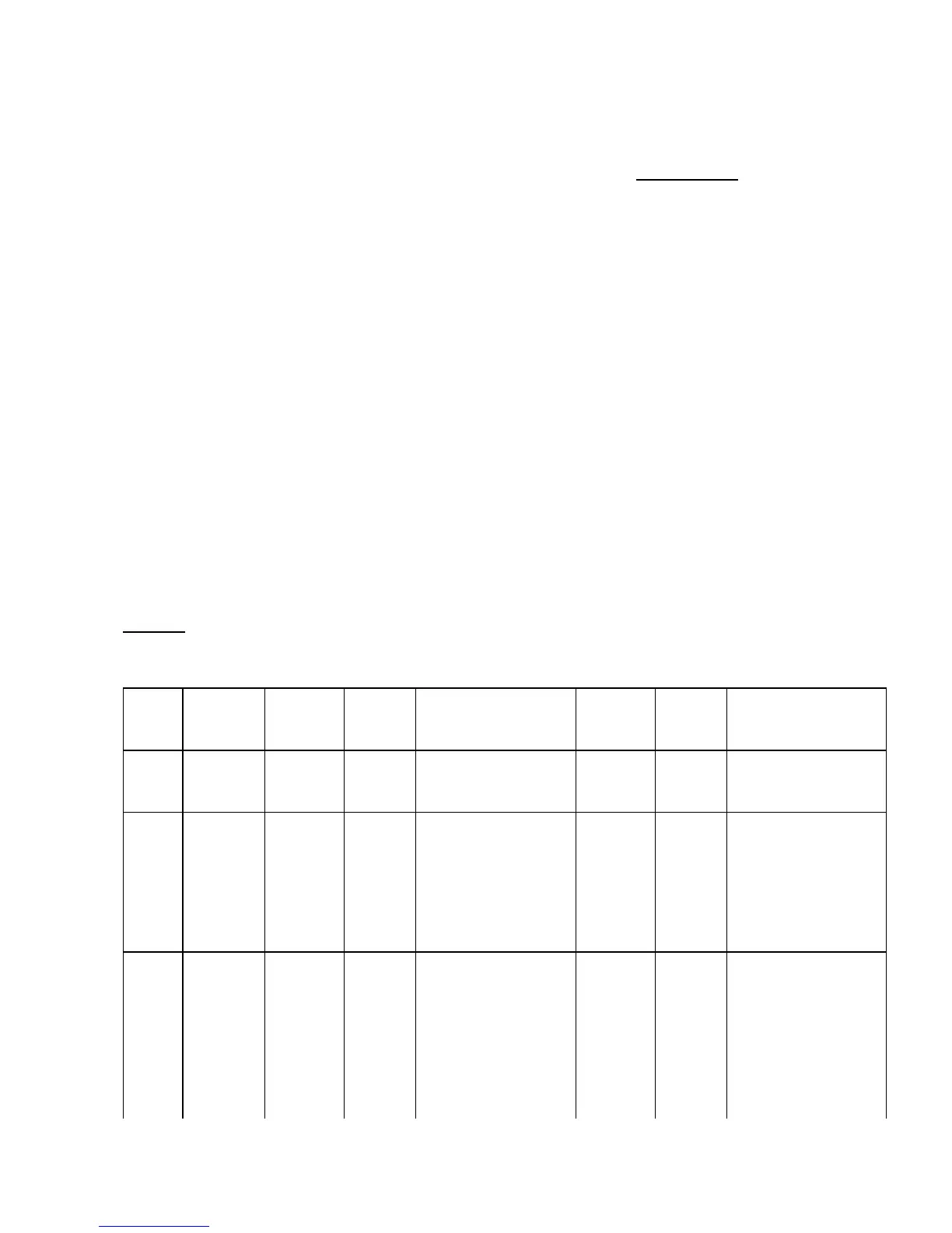
Table 1-1 shows the EIA types supported only by ONS 15454 shelf assembly 15454-SA-ANSI.
Table 1-1: EIA Types Compatible with the 15454-SA-ANSI Only
EIA
Type
Cards
Supported
A-Side
Hosts
A-Side
Columns
Map to
A-Side Product
Number
B-Side
Hosts
B-Side
Columns
Map to
B-Side Product
Number
BNC
DS-3
DS3XM-6
EC-1
24 pairs of
BNC
connectors
Slot 2
Slot 4
15454-EIA-BNC-A24=
24 pairs of
BNC
connectors
Slot 14
Slot 16
15454-EIA-BNC-B24=
High-
Density
BNC
DS-3
DS3XM-6
EC-1
48 pairs of
BNC
connectors
Slot 1
Slot 2
Slot 4
Slot 5
15454-EIA-BNC-A48=
48 pairs of
BNC
connectors
Slot 13
Slot 14
Slot 16
Slot 17
15454-EIA-BNC-B48=
SMB DS-1
DS-3
EC-1
DS3XM-6
84 pairs of
SMB
connectors
Slot 1
Slot 2
Slot 3
Slot 4
15454-EIA-SMB-A84= 84 pairs of
SMB
connectors
Slot 12
Slot 13
Slot 14
Slot 15
15454-EIA-SMB-B84=
ONS_15454_Reference_Manual_R8.5.x_--_Shelf_and_Backplane_Hardware
Electrical Interface Assemblies 15

 Loading...


