Each AEP alarm input port has provisionable label and severity. The alarm inputs have optocoupler isolation.
They have one common 48-VDC output and a maximum of 2 mA per input. Each opto metal oxide
semiconductor (MOS) alarm output can operate by definable alarm condition, a maximum open circuit
voltage of 60 VDC, anda maximum current of 100 mA. See the External Alarms and Controls for further
information.
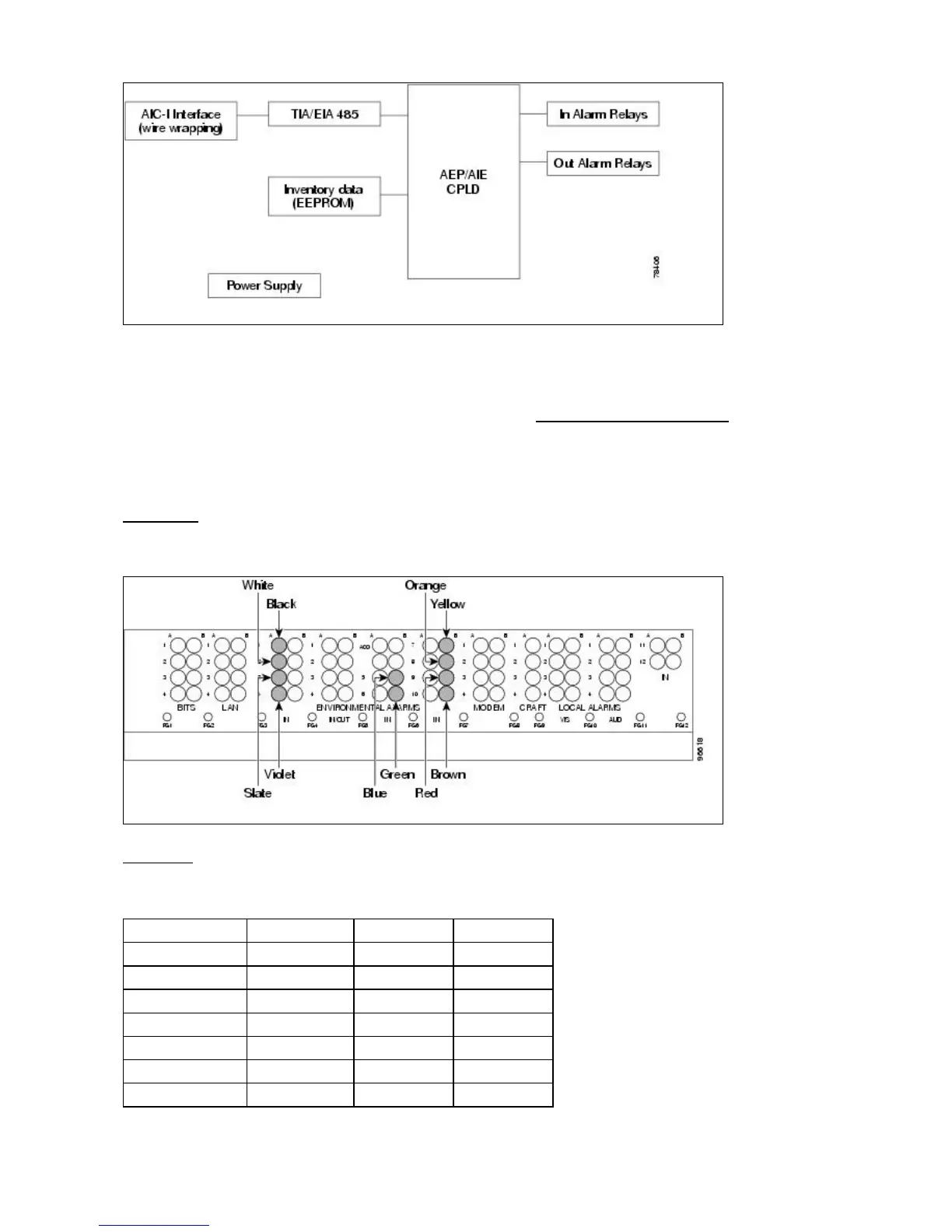
Wire-Wrap and Pin Connections
Figure 1-33 shows the wire-wrapping connections on the backplane.
Figure 1-33: AEP Wire-Wrap Connections to Backplane Pins
Table 1-22 shows the backplane pin assignments and corresponding signals on the AIC-I and AEP.
Table 1-22: Pin Assignments for the AEP
AEP Cable Wire Backplane Pin AIC-I Signal AEP Signal
Black A1 GND AEP_GND
White A2 AE_+5 AEP_+5
Slate A3 VBAT- VBAT-
Violet A4 VB+ VB+
Blue A5 AE_CLK_P AE_CLK_P
Green A6 AE_CLK_N AE_CLK_N
Yellow A7 AE_DIN_P AE_DOUT_P
ONS_15454_Reference_Manual_R8.5.x_--_Shelf_and_Backplane_Hardware
Figure 1-32: AEP Block Diagram 44

 Loading...


