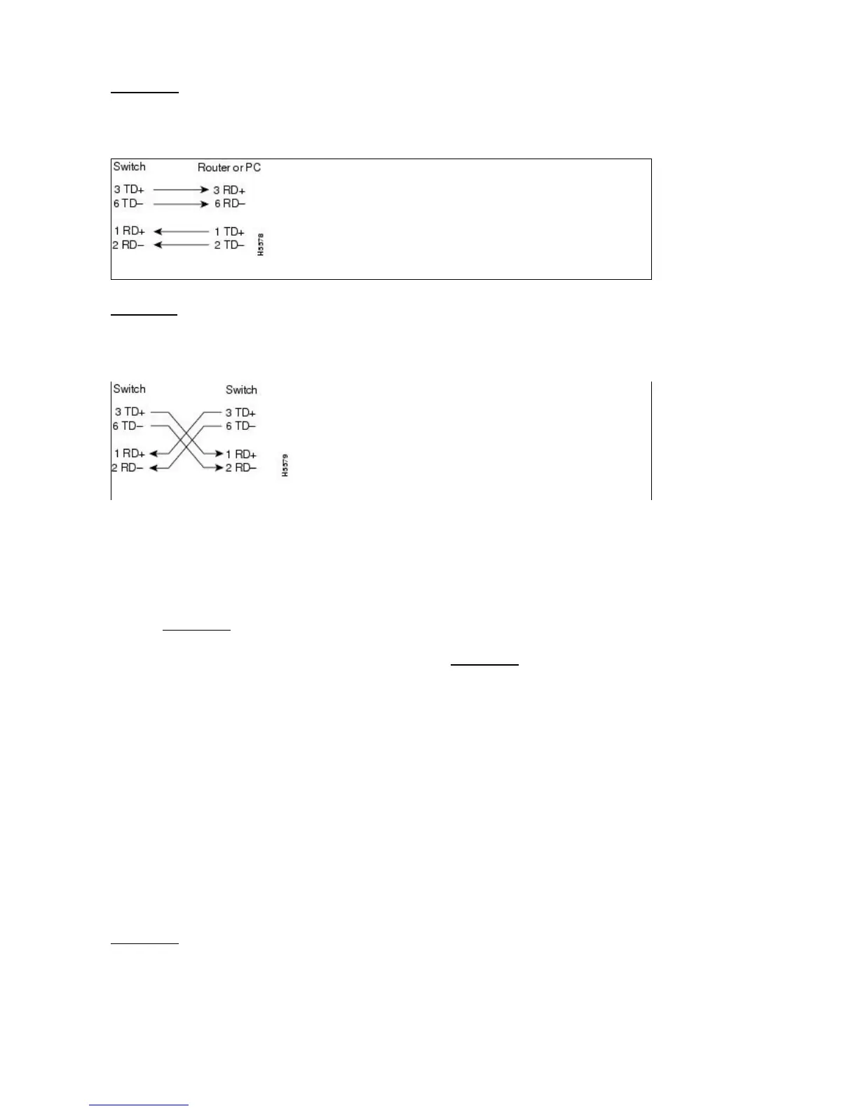
Figure 1-26 shows the straight-through Ethernet cable schematic. Use a straight-through cable when
connecting to a router or a PC.
Figure 1-26: Straight-Through Cable
Figure 1.27 shows the crossover Ethernet cable schematic. Use a crossover cable when connecting to a
switch or hub.
Figure 1-27: Crossover Cable
Cable Routing and Management
The ONS 15454 cable management facilities include the following:
A cable-routing channel (behind the fold-down door) that runs the width of the shelf assembly
(Figure 1-28)
•
Plastic horseshoe-shaped fiber guides at each side opening of the cable-routing channel that ensure
the proper bend radius is maintained in the fibers (Figure 1-29)
•
Note: You can remove the fiber guide if necessary to create a larger opening (if you need to route CAT-5
Ethernet cables out the side, for example). To remove the fiber guide, take out the three screws that anchor it
to the side of the shelf assembly.
A fold-down door that provides access to the cable-management tray•
Cable tie-wrap facilities on EIAs that secure cables to the cover panel•
A cable routing channel that enables you to route cables out either side•
Jumper slack storage reels (2) on each side panel that reduce the amount of slack in cables that are
connected to other devices
•
Note: To remove the jumper slack storage reels, take out the screw in the center of each reel.
Optional tie-down bar•
Figure 1-28 shows the cable management facilities that you can access through the fold-down front door,
including the cable-routing channel and cable-routing channel posts.
ONS_15454_Reference_Manual_R8.5.x_--_Shelf_and_Backplane_Hardware
Figure 1-25: 100BaseT Connector Pins 40

 Loading...


