EasyManuals Logo

Cisco ONS 15454 Series Reference Manual

Cisco ONS 15454 Series
64 pages
To Next Page IconTo Next Page
To Previous Page IconTo Previous Page
Page #41 background imageLoading...
Page #41 background image
Figure 1-28: Managing Cables on the Front Panel
Fiber Management
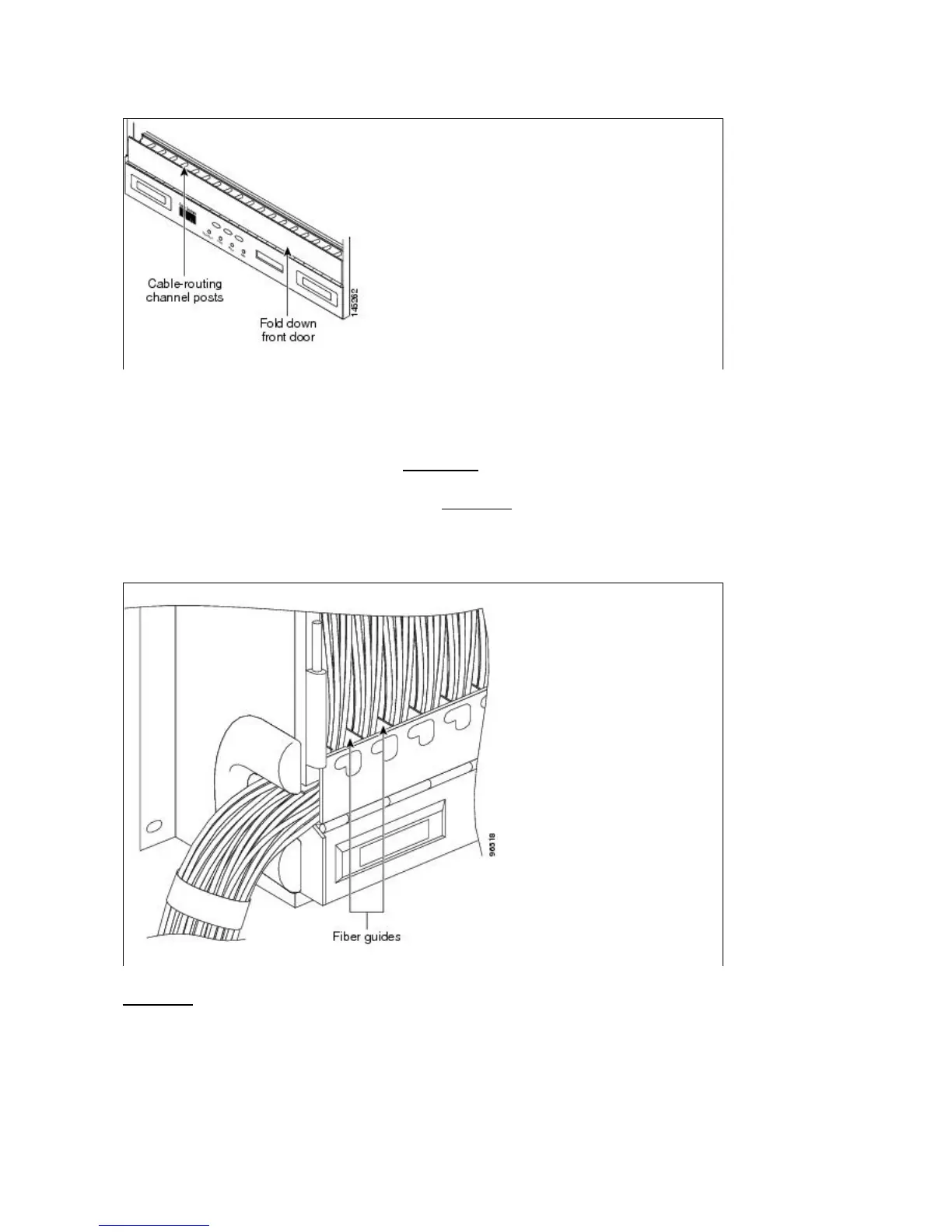
The jumper routing fins are designed to route fiber jumpers out of both sides of the shelf. Slots 1 to 6 exit to
the left, and Slots 12 to 17 exit to the right. Figure 1-29 shows fibers routed from cards in the left slots, down
through the fins, then exiting out the fiber channel to the left. The maximum capacity of the fiber routing
channel depends on the size of the fiber jumpers. Table 1-21 gives the maximum capacity of the fiber
channel for each side of the shelf, for the different fiber sizes.
Figure 1-29: Fiber Capacity
Table 1-21 provides the maximum capacity of the fiber channel for one side of a shelf, depending on fiber
size and number of Ethernet cables running through that fiber channel.
ONS_15454_Reference_Manual_R8.5.x_--_Shelf_and_Backplane_Hardware
Figure 1-28: Managing Cables on the Front Panel 41

Other manuals for Cisco ONS 15454 Series

Questions and Answers:

Question and Answer IconNeed help?

Do you have a question about the Cisco ONS 15454 Series and is the answer not in the manual?

Cisco ONS 15454 Series Specifications

General IconGeneral
Supported InterfacesEthernet
ManagementCisco Transport Controller (CTC), TL1, SNMP
Power Supply-48 VDC or AC (depending on power supply module)
Operating Temperature0 to 50°C (32 to 122°F) - varies by module
Storage Temperature-40°C to 70°C (-40 to 158°F)
Relative Humidity5 to 95%, noncondensing
Supported ProtocolsSONET/SDH, Ethernet, OTN
Platform TypeMulti-service transport platform

Related product manuals