20 GND 46 ALARM_IN_26-
21 ALARM_IN_27- 47 ALARM_IN_28-
22 ALARM_IN_29- 48 GND
23 GND 49 ALARM_IN_30-
24 ALARM_IN_31- 50 N.C.
25 ALARM_IN_+ 51 GND1
26 ALARM_IN_0- 52 GND2
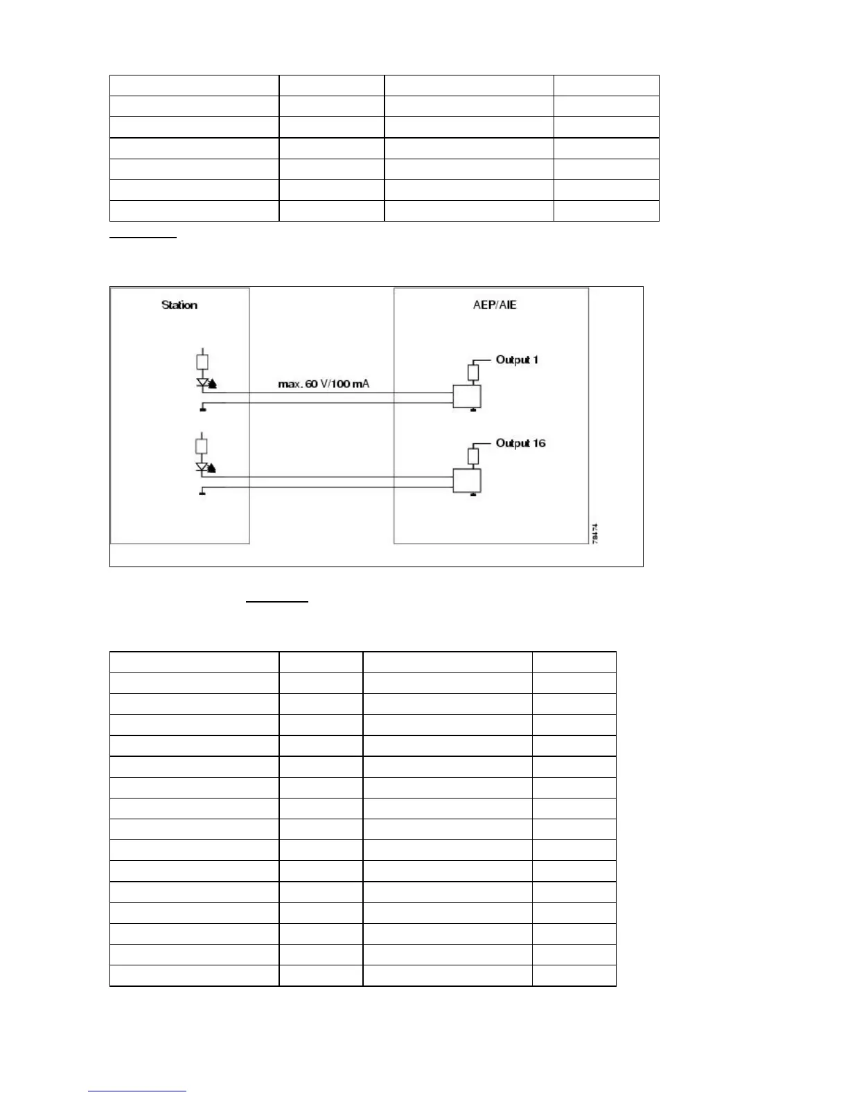
Figure 1-35 is a circuit diagram of the alarm outputs (Outputs 1 and 16 are shown in the example).
Figure 1-35: Alarm Output Circuit Diagram
Use the pin numbers in Table 1-24 to connect to the external elements being switched by external alarms.
Table 1-24: Pin Association for Alarm Output Pins
AMP Champ Pin Number Signal Name AMP Champ Pin Number Signal Name
1 N.C. 27 COM_0
2 COM_1 28 N.C.
3 NO_1 29 NO_2
4 N.C. 30 COM_2
5 COM_3 31 N.C.
6 NO_3 32 NO_4
7 N.C. 33 COM_4
8 COM_5 34 N.C.
9 NO_5 35 NO_6
10 N.C. 36 COM_6
11 COM_7 37 N.C.
12 NO_7 38 NO_8
13 N.C. 39 COM_8
14 COM_9 40 N.C.
15 NO_9 41 NO_10
ONS_15454_Reference_Manual_R8.5.x_--_Shelf_and_Backplane_Hardware
Table 1-23: Alarm Input Pin Association 46

 Loading...


