25 13 50 14
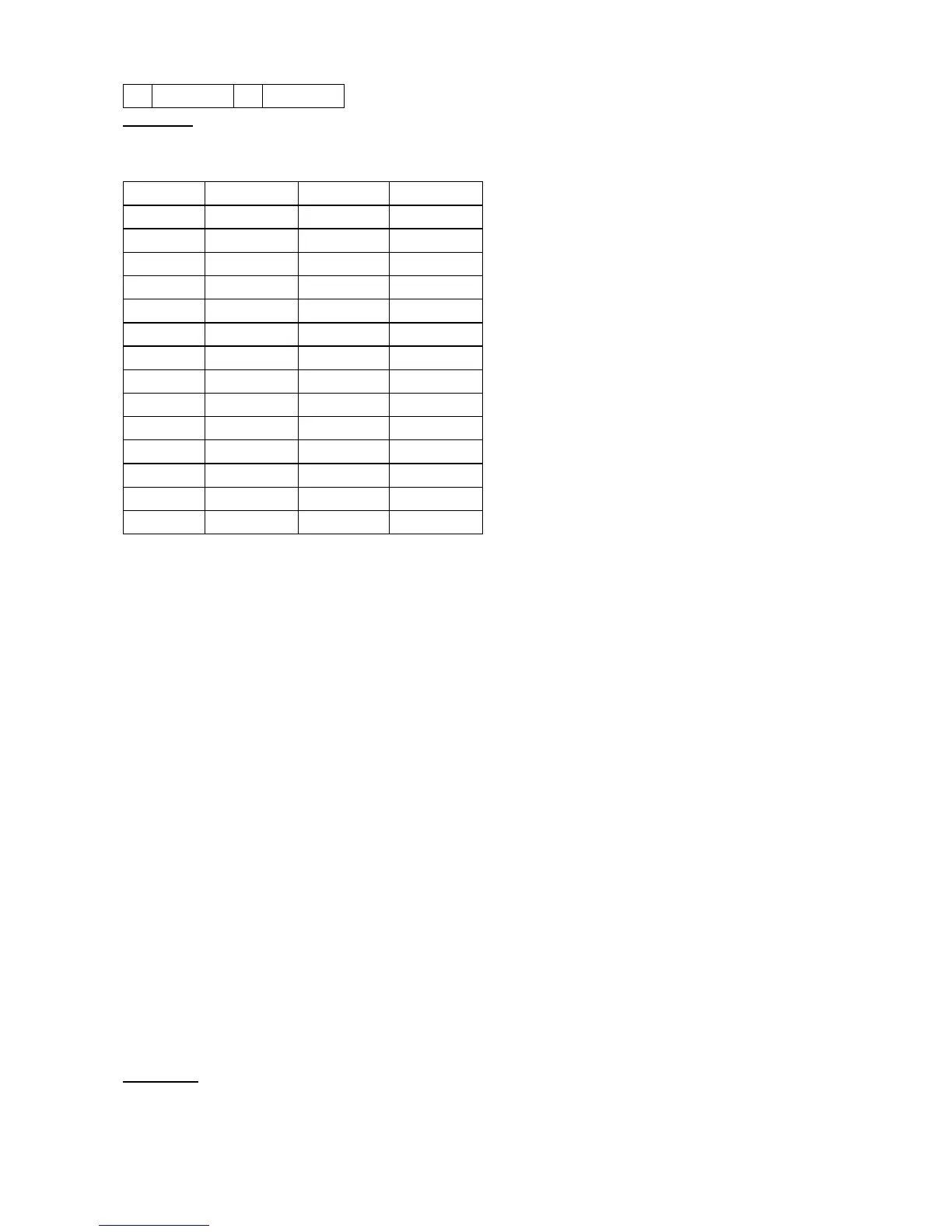
Table 1-17 shows the UBIC-V EIA DS-1 cable wiring.
Table 1-17: UBIC-V EIA DS-1 Wiring
Signal Wire Color Signal Wire Color
Tip Port 1 White/blue Ring Port 1 Blue/white
Tip Port 2 White/orange Ring Port 2 Orange/white
Tip Port 3 White/green Ring Port 3 Green/white
Tip Port 4 White/brown Ring Port 4 Brown/white
Tip Port 5 White/slate Ring Port 5 Slate/white
Tip Port 6 Red/blue Ring Port 6 Blue/red
Tip Port 7 Red/orange Ring Port 7 Orange/red
Tip Port 8 Red/green Ring Port 8 Green/red
Tip Port 9 Red/brown Ring Port 9 Brown/red
Tip Port 10 Red/slate Ring Port 10 Slate/red
Tip Port 11 Black/blue Ring Port 11 Blue/black
Tip Port 12 Black/orange Ring Port 12 Orange/black
Tip Port 13 Black/green Ring Port 13 Green/black
Tip Port 14 Black/brown Ring Port 14 Brown/black
UBIC-H Cables
The UBIC-H EIA is designed to support DS-1, DS-3, or EC-1 signals. The type of signal supported is
determined by the UBIC-H cable assembly selected. To support DS-1 signals, select the DS-1 UBIC-H cable
assembly (part number 15454-CADS1-H-length>). For DS-3 or EC-1 signals, select the DS-3/EC-1 UBIC-H
cable assembly (part number 15454-CADS3-H-length>).
DS-1 cables for the UBIC-H have a maximum supported distance of 655 feet. The following DS-1 cables are
available from Cisco Systems for use with the UBIC-H EIA:
25 feet: 15454-CADS1-H-25•
50 feet: 15454-CADS1-H-50•
75 feet: 15454-CADS1-H-75•
100 feet: 15454-CADS1-H-100•
150 feet: 15454-CADS1-H-150•
200 feet: 15454-CADS1-H-200•
250 feet: 15454-CADS1-H-250•
350 feet: 15454-CADS1-H-350•
450 feet: 15454-CADS1-H-450•
DS-3/EC-1 cables for the UBIC-H have a maximum supported distance of 450 feet. The following
DS-3/EC-1 cables are available from Cisco Systems for use with the UBIC-H EIA:
75 feet: 15454-CADS3-SD•
225 feet: 15454-CADS3-ID•
450 feet: 15454-CADS3-LD•
Figure 1-24 shows the pin locations on the DS-1 and DS-3/EC-1 SCSI connectors.
ONS_15454_Reference_Manual_R8.5.x_--_Shelf_and_Backplane_Hardware
Table 1-16: UBIC-V DS-1 and DS-3/EC-1 Pin Assignments 37

 Loading...


