EasyManuals Logo

Cisco ONS 15454 Series Reference Manual

Cisco ONS 15454 Series
64 pages
To Next Page IconTo Next Page
To Previous Page IconTo Previous Page
Page #13 background imageLoading...
Page #13 background image
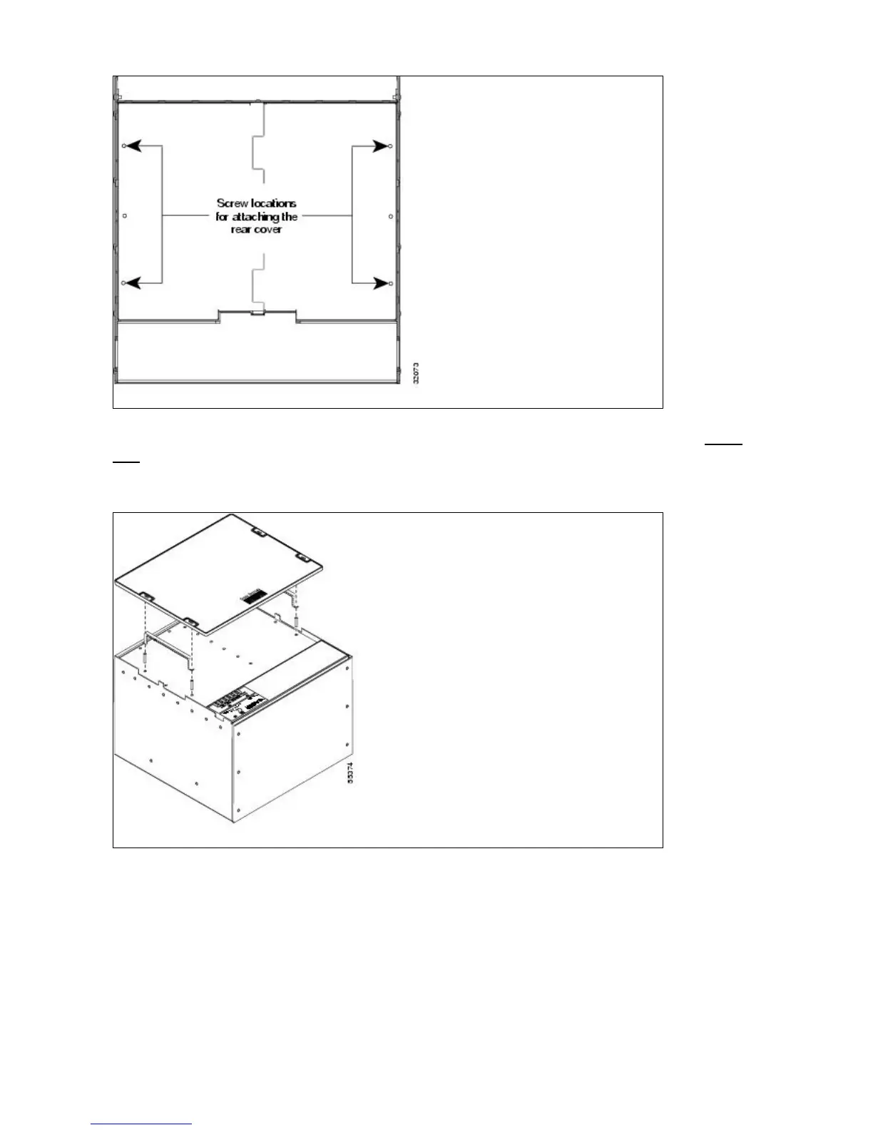
You can also install the optional spacers if more space is needed between the cables and rear cover (Figure
1-12).
Figure 1-12: Installing the Plastic Rear Cover with Spacers
Alarm Interface Panel
The AIP is located above the alarm contacts on the lower section of the backplane. The AIP provides surge
protection for the ONS 15454. It also provides an interface from the backplane to the fan-tray assembly and
LCD. The AIP plugs into the backplane using a 96-pin DIN connector and is held in place with two retaining
screws. The panel has a nonvolatile memory chip that stores the unique node address (MAC address).
ONS_15454_Reference_Manual_R8.5.x_--_Shelf_and_Backplane_Hardware
Figure 1-11: Backplane Attachment for Cover 13

Other manuals for Cisco ONS 15454 Series

Questions and Answers:

Question and Answer IconNeed help?

Do you have a question about the Cisco ONS 15454 Series and is the answer not in the manual?

Cisco ONS 15454 Series Specifications

General IconGeneral
Supported InterfacesEthernet
ManagementCisco Transport Controller (CTC), TL1, SNMP
Power Supply-48 VDC or AC (depending on power supply module)
Operating Temperature0 to 50°C (32 to 122°F) - varies by module
Storage Temperature-40°C to 70°C (-40 to 158°F)
Relative Humidity5 to 95%, noncondensing
Supported ProtocolsSONET/SDH, Ethernet, OTN
Platform TypeMulti-service transport platform

Related product manuals