1-30
Cisco ONS 15454 Procedure Guide, R4.0
March 2003
Chapter 1 Install the Shelf and Backplane Cable
NTP-A7 Install the Fan-Tray Assembly
Caution You must place the edge of the air filter flush against the front of the fan-tray assembly compartment
when installing the fan tray on top of the filter. Failure to do so could result in damage to the filter, the
fan tray, or both.
Caution Do not force a fan-tray assembly into place. Doing so can damage the connectors on the fan tray and/or
the connectors on the back panel of the shelf assembly.
Note To install the fan-tray assembly, it is not necessary to move any of the cable-management facilities.
Step 1 Slide the fan tray into the shelf assembly until the electrical plug at the rear of the tray plugs into the
corresponding receptacle on the backplane.
Step 2 To verify that the tray has plugged into the backplane, ensure that the LCD on the front of the fan tray
is activated and displays data.
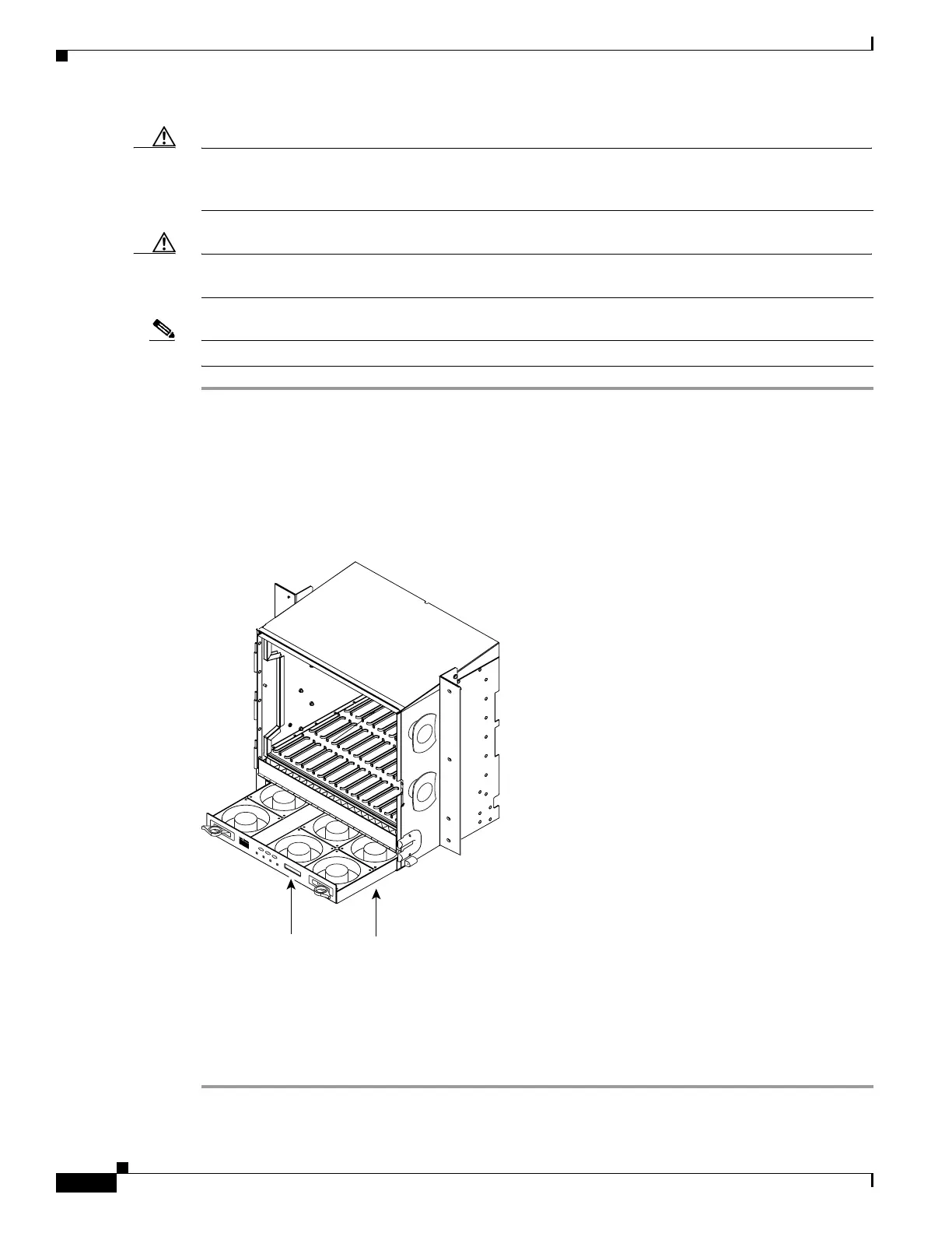
Figure 1-11 shows the location of the fan tray.
Figure 1-11 Installing the Fan-Tray Assembly
Step 3 Continue with the “NTP-A119 Install the Alarm Expansion Panel” procedure on page 1-31 if you plan
to install an Alarm Expansion Panel (AEP). If not, continue with the “NTP-A8 Install Wires to Alarm,
Timing, LAN, and Craft Pin Connections” procedure on page 1-34.
Stop. You have completed this procedure.
FAN FAIL
CRIT
MAJ
MIN
38532
Fan tray
assembly
LCD

 Loading...


