6-11
Cisco SCE8000 GBE Installation and Configuration Guide
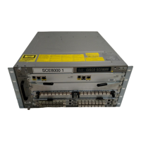
Chapter 6 Cabling the Line Ports and Completing the Installation
Cabling the 10 GBE Line Interface Ports
Cabling the 10 GBE Line Interface Ports
Note When installing an External Optical Bypass module, the Cisco SCE 8000 line ports are connected to the
module. See the Cabling the 10 GBE Line Interface Ports: Using the External Optical Bypass Module,
page 6-14 for complete instructions.
Warning
Class 1 laser. Avoid exposure to radiation and do not stare into open aperture.
Statement 1008
This section describes the following topics:
• XFP Module Cabling and Connection Equipment, page 6-11
• Optical Device Maintenance, page 6-12
• How to Cable the 10 GBE Line Interface Ports, page 6-13
• Cabling the 10 GBE Line Interface Ports: Using the External Optical Bypass Module, page 6-14
XFP Module Cabling and Connection Equipment
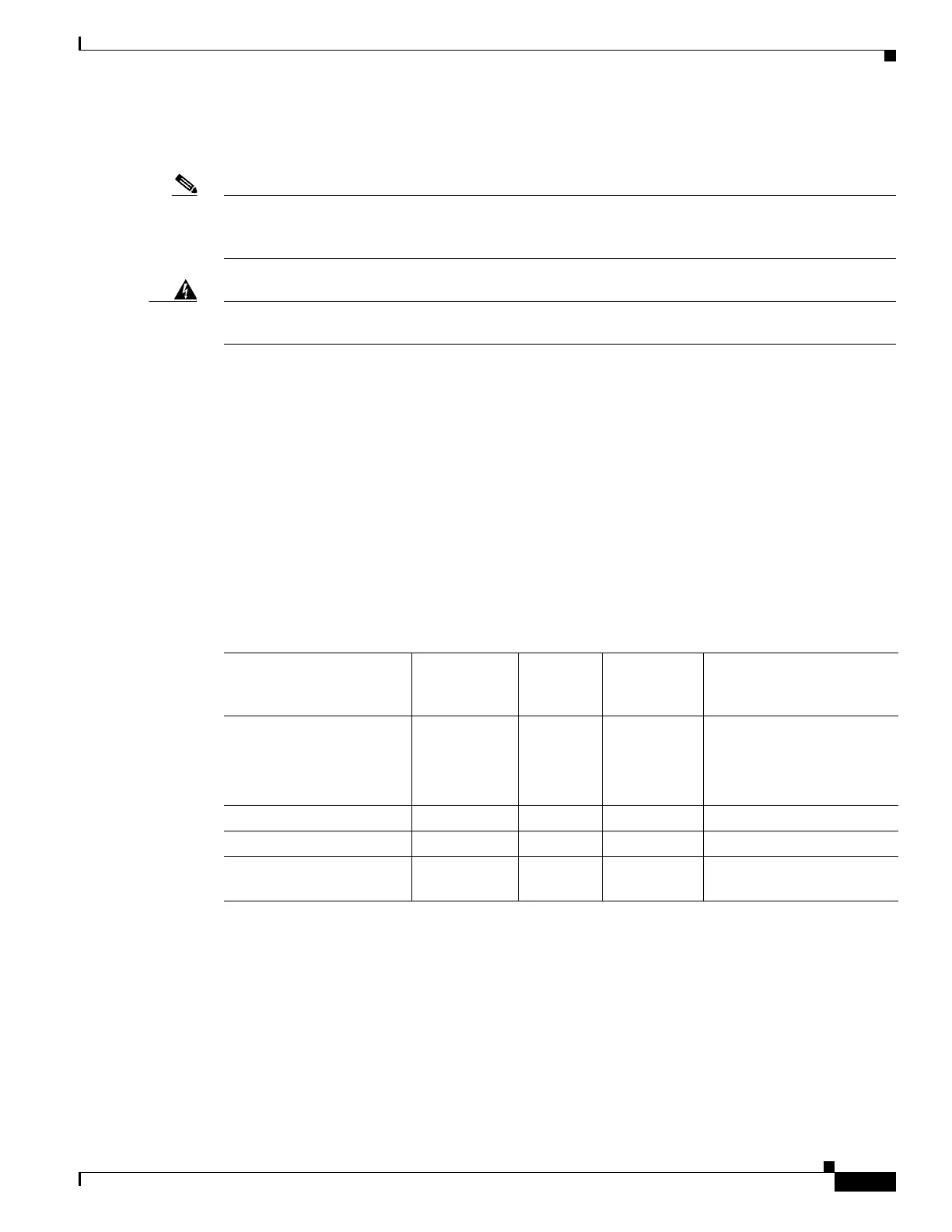
Table 6-1 and Table 6-2 provide cabling specifications for the XFP modules that can be installed on the
10 Gigabit Ethernet SPA. All XFP ports have LC-type connectors.
Table 6-1 XFP Transceiver Port Cabling Specifications
XFP Product Number
Nominal
Wavelength
(nm) Cable Type
Core Size
(microns) Maximum Cabling Distance
XFP-10GLR-OC192SR 1310 SMF G.652
• 10 km (6.2 miles)
10-Gigabit Ethernet
• 2 km (1.24 miles)
OC-192/STM-64 SR1
XFP-10GER-OC192IR 1550 SMF G.652 40 km (24.86 miles)
XFP-10GZR-OC192IR 1550 SMF G.652 80 km (10 miles)
XFP-10G-MM-SR 850 MMF G.652 26 m to 300 m
(85.3 to 984.3 feet)